CHAPTER 11 (2): PHASORS AND COMPLEX NUMBER
Complex Numbers and Phasors
Overview
Focus on phasors and complex numbers, critical in analyzing AC circuits.
Representation of AC voltages and applications in circuit analysis.
Objectives
Use phasors to represent sine waves.
Represent phasors using complex numbers.
Perform calculations with rectangular and polar forms.
Convert between polar and rectangular forms.
Determine total output voltage of AC sources connected in series.
Complex Number System
Phasors initially graphical; complex numbers allow mathematical manipulation.
Complex numbers facilitate addition, subtraction, multiplication, and division of phasors.
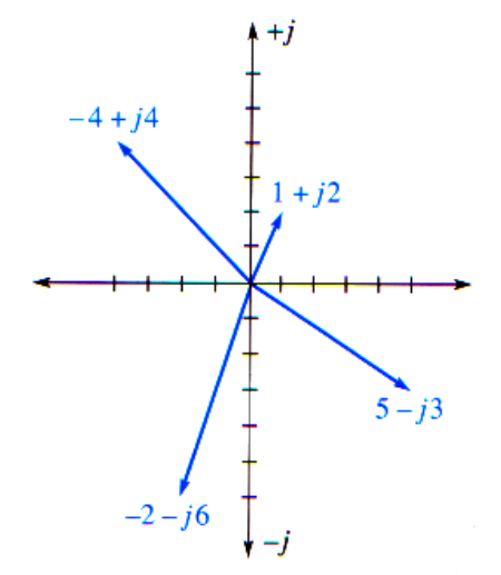
Rectangular and Polar Forms
Rectangular Form
Represents phasor as: A + jB
A: real value
jB: imaginary component
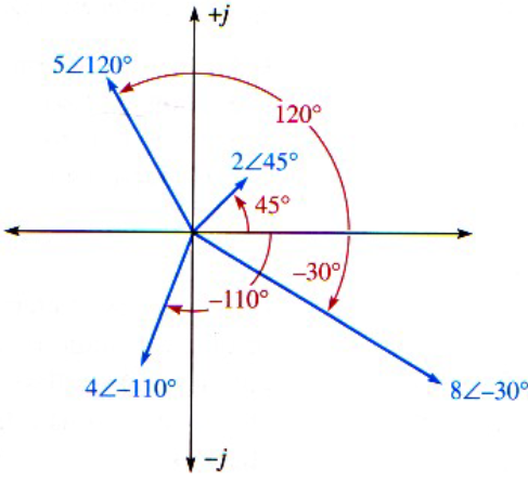
Polar Form
Represents phasor as: C ∠ ±q
C: magnitude of the phasor
q: angular position relative to the positive real axis
Mathematical Operations (similar operations to EM1)
Addition & Subtraction
Complex numbers must be in rectangular form.
Add or subtract real and imaginary parts separately.
Multiplication & Division
For polar forms: multiply magnitudes and add/subtract angles.
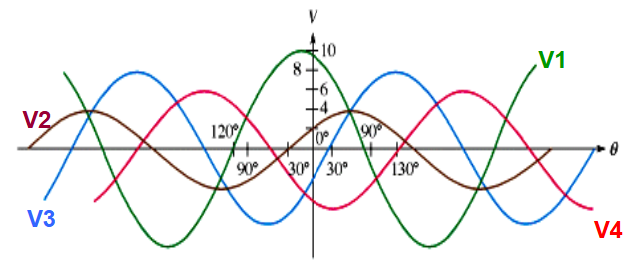
Example of Sine Waves
Different sinusoidal AC voltages represented: (rectangular form)
v1 = 10 sin(ωt + 120°)
v2 = 4 sin(ωt + 30°)
v3 = 8 sin(ωt - 30°)
v4 = 6 sin(ωt - 130°)
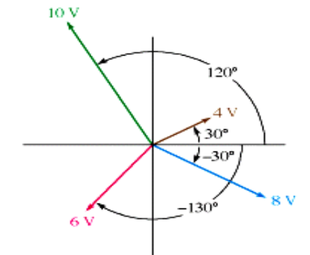
Converted to polar form using peak voltages: (polar form)
v1(peak) = 10∠ 120°
v2(peak) = 4 ∠ 30°
v3(peak) = 8 ∠ -30°
v4(peak) = 6 ∠ -130°
Total Voltage Calculation
When connected in series, total voltage formula:
Vtotal(peak) = V1(peak) + V2(peak) + V3(peak) + V4(peak)
Resulting calculation includes converting values to rectangular form and summing: (just use calculator to convert)
Total represented as: Vtotal = 2.57 ∠ 53.4° = 2.57 sin (ωt + 53.4°)
Important Note on RMS Values
AC voltages and currents typically described by RMS (Root Mean Square) values.
Magnitudes of phasors in AC circuit analysis represent RMS values unless stated otherwise.
Summary of Phasor and Complex Number Characteristics
Phasor Diagrams:
Represent sine waves with angular positions indicating phase and lengths indicating amplitude.
Forms of Complex Numbers:
Rectangular: A + jB, with real and imaginary parts.
Polar: C ∠ θ, with magnitude and angle.
End of Chapter 11
Concludes discussions on phasors and complex numbers.