Comprehensive Guide to Capacitors & Dielectrics
Understanding Capacitance
At its core, a capacitor is a device used to store electric potential energy by separating electric charge. It typically consists of two conducting objects (plates) separated by an insulating gap.
The Definition of Capacitance
Capacitance () is the measure of a system's ability to store electric charge per unit ot potential difference.
Mathematically, it is defined as the ratio of the magnitude of the charge on one conductor to the magnitude of the potential difference between the conductors:
- : The magnitude of charge on one of the plates (since net charge is usually zero: and ).
- : The potential difference (voltage) across the plates.
- Unit: The SI unit is the Farad (F). Since is a very large amount of capacitance, we typically see microfarads () or picofarads ().
Key Concept: Capacitance is strictly a geometric property. It depends on the size, shape, and spacing of the conductors and the material between them—not on or individually. If you double the voltage, you double the charge stored, but remains constant.
Parallel Plate Capacitors
The most common capacitor geometry analyzed in AP Physics C is the parallel plate capacitor. This consists of two parallel conducting plates of area separated by a small distance .
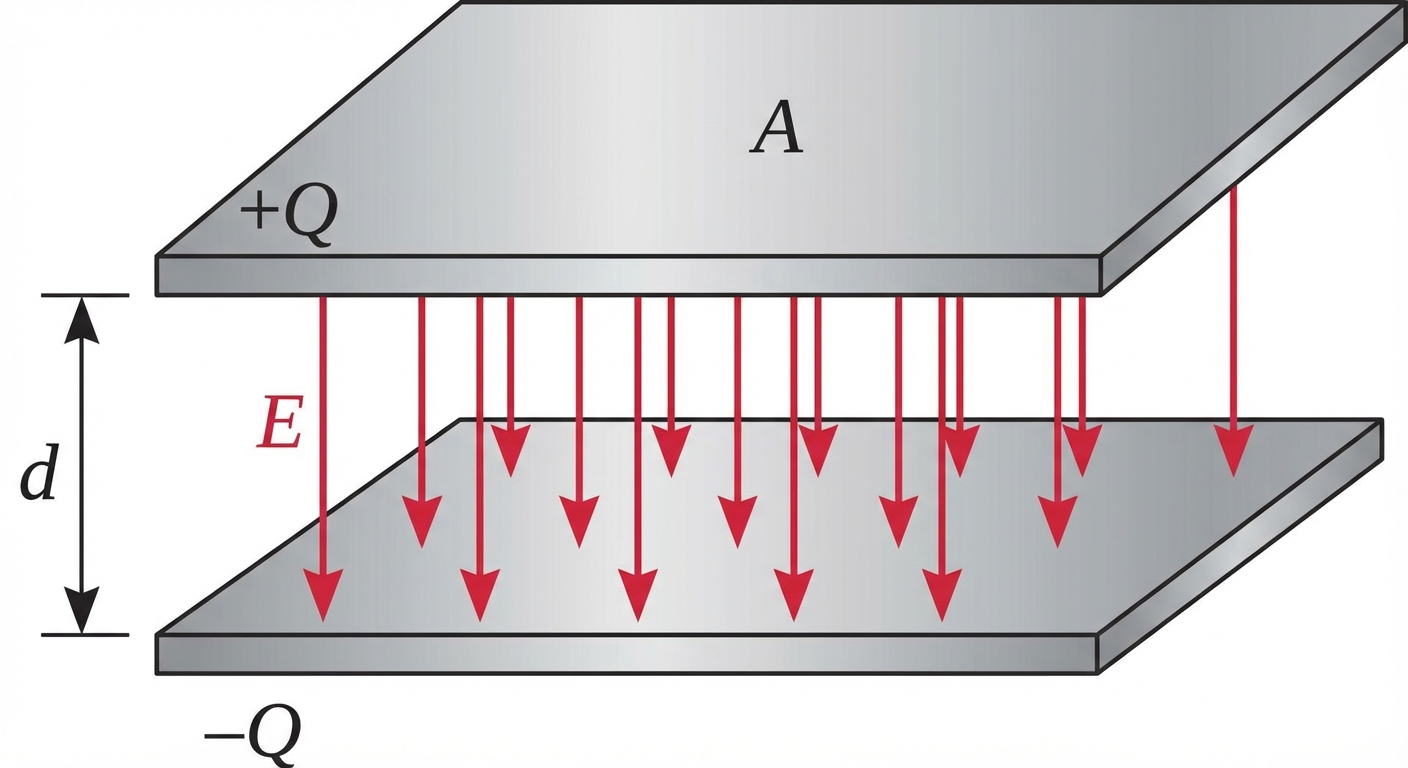
Deriving Capacitance for Parallel Plates
To derive the capacitance, we follow a standard three-step process using Gauss's Law and the relationship between potential and field.
Find Electric Field ():
Assuming the plates are very large compared to , we treat them as infinite sheets. The field between the plates is uniform.Find Potential Difference ():
We integrate the electric field across the gap distance .Solve for :
Using the definition :
Here, is the vacuum permittivity ().
Other Geometries (Calculus Required)
In AP Physics C, you must be comfortable deriving capacitance for other shapes (spherical, cylindrical) using the integration method: .
- Spherical Capacitor: Two concentric shells of radii and .
- Cylindrical Capacitor: Two concentric cylinders of radii and and length .
Dielectrics
A dielectric is an insulating material inserted between the plates of a capacitor. Dielectrics serve two main purposes: they physically separate the plates and they increase the capacitance.
Dielectric Constant ()
The factor by which the capacitance increases is called the dielectric constant (, kappa). For vacuum, ; for all other materials, .
Atomic Mechanism: Polarization
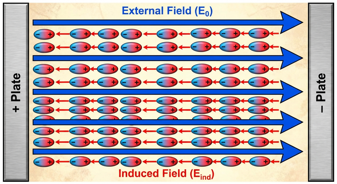
Why does a dielectric increase capacitance? When placed in an external electric field (from the capacitor plates), the molecules in the dielectric material induce a dipole moment. This is known as polarization.
- The positive nuclei are pushed gently with the field, and electron clouds are pulled against it.
- This creates a small internal electric field inside the dielectric, , which opposes the external field.
- The net field inside the material is reduced:
Impact on Variables
How a dielectric affects , , and depends on the circuit context:
| Condition | Charge () | Voltage () | Capacitance () | Electric Field () | Energy () |
|---|---|---|---|---|---|
| Battery Disconnected (Isolated) | Constant | Decreases () | Increases () | Decreases () | Decreases () |
| Battery Connected (Constant V) | Increases () | Constant | Increases () | Constant | Increases () |
Energy Stored in Capacitors
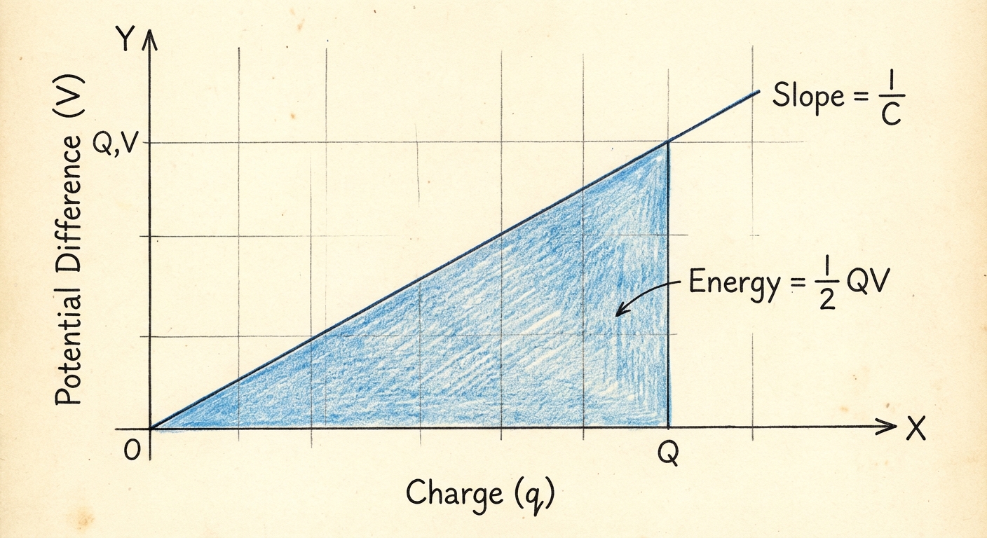
Capacitors store energy in the electric field created between the plates. To charge a capacitor, an external agent (like a battery) must do work to move charge against the accumulating potential difference.
Derivation via Work
The work done to move a small charge element across a potential difference is:
Substituting and integrating from charge 0 to total charge :
Energy Formulas
Since , we can express the stored potential energy () in three equivalent forms. Memorize all three:
Energy Density ()
Sometimes we need to calculate the energy stored per unit volume (energy density). This is relevant for electromagnetic waves.
Substituting and :
This implies that the energy resides in the electric field itself.
Common Mistakes & Pitfalls
- Net vs. Plate Charge: Students often think in the formula is the net charge of the device. The net charge of a capacitor is zero. refers to the magnitude of excess charge on a single plate.
- Dielectric Logic: A common exam trap asks what happens to the electric field when a dielectric is inserted while the capacitor is still connected to a battery.
- Incorrect Instinct: Field decreases because dielectrics reduce field.
- Correct Physics: Since is fixed by the battery and is fixed, must remain constant. The battery pumps more charge onto the plates to overcome the dielectric opposition and maintain the field strength.
- Confusion with Resistance: When looking at capacitor combinations (Unit 3), remember the rules are opposite to resistors. Capacitors in Series add inversely (), and capacitors in Parallel add directly ().
- Ignoring Edge Effects: In derivations, we assume infinite plates to ignore fringing fields at the edges. While usually ignored in calculation, conceptually understanding that lines curve at the edges is important for conceptual questions.