3. Waves
Waves Overview
Types of Waves
Transverse Waves:
Direction of vibration is perpendicular to the direction of energy transfer.
Examples: Water waves, seismic secondary waves, electromagnetic waves.
Characteristics:
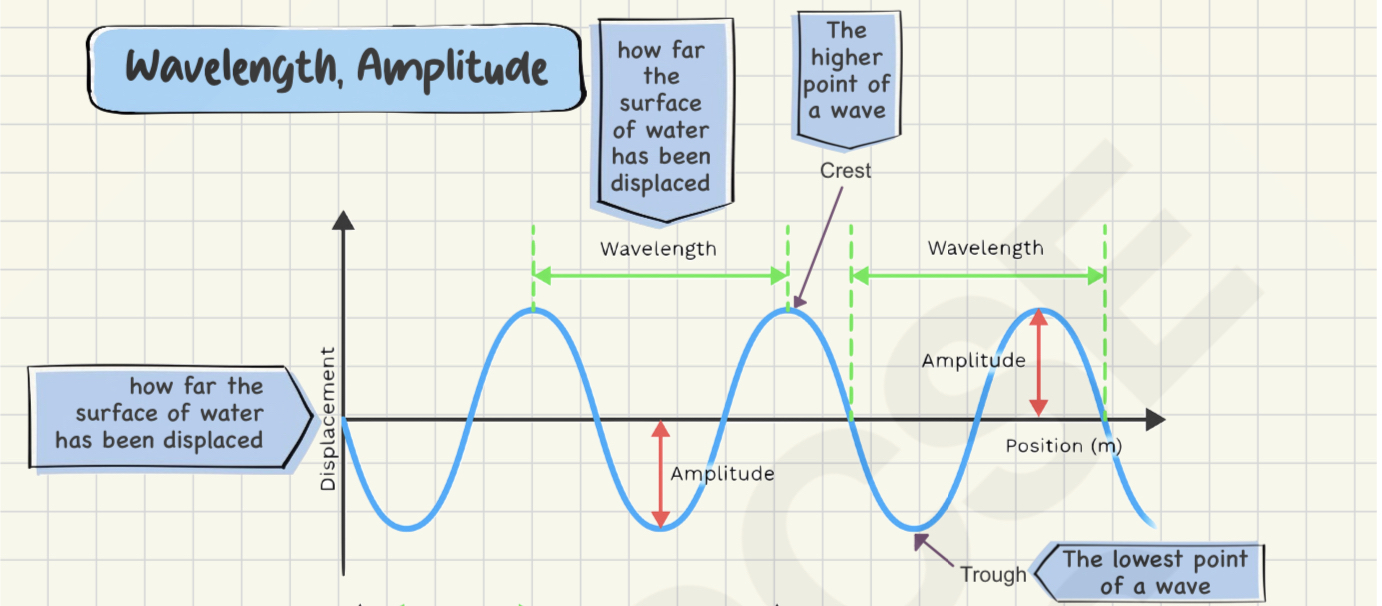
Crest: Highest point.
Trough: Lowest point.
Demonstrated by shaking a spring up and down.
Longitudinal Waves:
Direction of vibration is parallel to the direction of energy transfer.
Examples: Sound waves, seismic primary waves.
Characteristics:
Compression: Regions where particles are close together.
Rarefaction: Regions where particles are spread apart.
Demonstrated by shaking a spring back and forth.
Key Wave Properties
Property | Description | Measurement Units |
|---|---|---|
Amplitude | Distance from equilibrium to peak; indicates energy carried. | Meters (m) |
Wavelength | Distance between consecutive peaks or identical points. | Meters (m) |
Frequency | Number of vibrations per second. | Hertz (Hz) |
Period | Time taken for one complete wave cycle. | Seconds (s) |
Wave Speed | Distance traveled by wavefront per unit time. | Meters per second (m/s) |
Wave Behavior
Reflection:
Occurs when waves encounter an obstacle, changing direction while speed, wavelength, and frequency remain constant.
Law of Reflection: Angle of incidence equals angle of reflection.
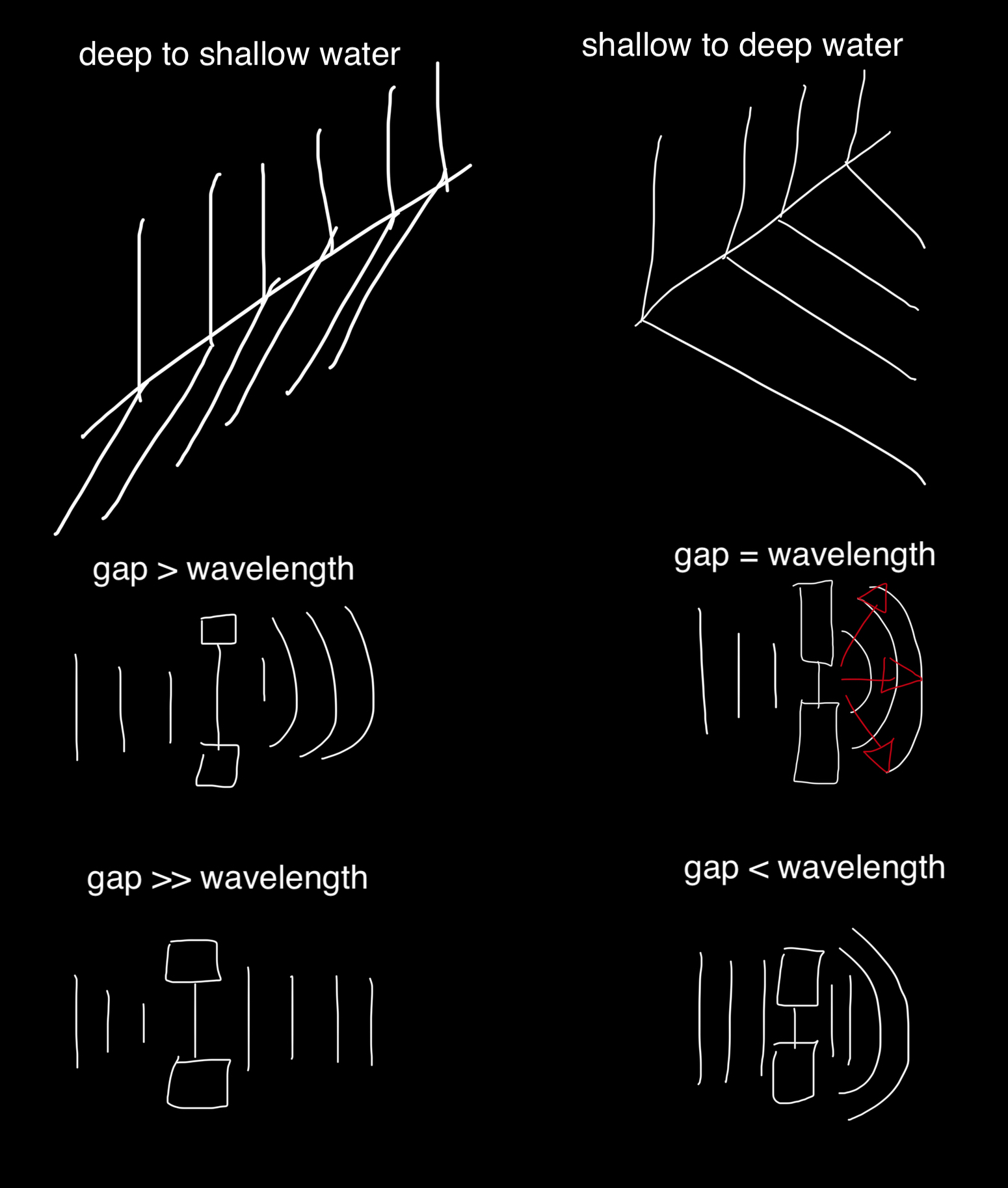
Refraction:
Change in wave direction when entering a different medium due to speed change.
Wavelength changes while frequency remains constant.
Diffraction:
Spreading of waves when passing through a gap or around an obstacle.
More diffraction occurs when the gap size is comparable to the wavelength.
Ripple Tank Demonstration
A ripple tank can visualize wave behaviors:
Wavefronts created by a vibrating dipper can be observed, with straight or circular formations.
Reflection and Refraction can be observed as waves encounter different mediums or obstacles.
Summary & Key Takeaways
Waves can be classified as transverse or longitudinal.
Key properties such as amplitude, wavelength, frequency, and speed are fundamental to understanding wave behavior.
Wave behaviors include reflection, refraction, and diffraction.
Key Concepts in Reflection
Normal: The perpendicular line to the surface at the point of incidence.
Angle of Incidence (I): The angle between the incident ray and the normal line.
Angle of Reflection (R): The angle between the reflected ray and the normal line; it is equal to the angle of incidence.
Formation of an Optical Image by a Plane Mirror
Characteristics of the Image:
Same Size: The image has the same dimensions as the object.
Same Distance: The image is located the same distance behind the mirror as the object is in front.
Upright: The image appears right-side up.
Virtual: The image cannot be projected onto a screen.
Diagram Construction Steps
Draw the Mirror: Represent the plane mirror.
Incident Ray: Draw a line from the top of the object to the mirror.
Normal Line: Perpendicular line to the mirror at the point of incidence.
Measure Angles: Measure the angles of incidence (I) and reflection (R); ensure both are equal.
Reflective Ray: Extend the reflective ray back as a dotted line to indicate it is virtual.
Second Incident Ray: Repeat the above steps to confirm image formation.
Properties of Light Waves
Nature: Light waves are transverse and electromagnetic waves.
Speed: The speed of light in a vacuum is approximately .
Travel Path: Light travels in straight lines and exhibits phenomena such as refraction and diffraction.
Summary & Practical Applications
Understand the basic principles of light reflection and image characteristics produced by a plane mirror.
Practice drawing diagrams illustrating light reflection, applying the principles of angles and distances.
Familiarize yourself with key definitions such as "virtual image," "angle of incidence," and "angle of reflection."
Refraction of Light
Bending of light as it passes from one medium to another.
Light slows down and bends towards the normal in a denser medium and speeds up, bending away from the normal in a less dense medium.
Angle Definitions:
Angle of Incidence (I): Angle between incident light ray and the normal.
Angle of Refraction (R): Angle between refracted light ray and the normal.
Wavelength and Speed
Wavelength changes with speed of light; as speed increases, wavelength increases, and vice versa.
Refractive Index (n): Ratio of the speed of light in vacuum (C) to the speed of light in the medium (V):
n = refractive index
c = speed of light in vacuum - it is always 3 × 10^8 m/s
v = speed of light in medium
Typical value for air: approximately 1; varies with material density.
Snell's Law
Describes the relationship between angles of incidence and refraction: n1sinθ1 = n2sinθ2
Practical Examples:
Light passing from air to glass (n1 = 1, n2 = 1.5) with an incidence of results in a refraction.
Example 1:
Example 2:
Example 3: Light from air to diamond at incidence; refractive index
Speed of light in diamond:
Experimental Setup for Refraction
Tracing Light Paths:
Shine a ray of light through a glass block and trace its path.
Measure angles of incidence and refraction to calculate the refractive index.
Repeat for various angles to find average values and plot graphs of sin I vs. sin R.
Critical Angle and Total Internal Reflection
Critical Angle (C): The angle of incidence in a denser medium where refraction angle equals
90° n = 1/sinCTotal Internal Reflection: Occurs when angle of incidence exceeds the critical angle, preventing light from refracting.
Applications of Total Internal Reflection
Periscopes: Utilize glass prisms to reflect light via total internal reflection.
Optical Fibers: Composed of a core and cladding that enable light transmission through total internal reflection, widely used in telecommunications and medical endoscopy.
Summary & Key Takeaways
Refraction governs how light interacts with materials, defined by Snell's Law and refractive indices.
Practical calculations of angles showcase the application of these properties.
Understanding total internal reflection enables innovative technologies such as optical fibers and prisms found in various instruments.
Key Concepts
Lenses: Optical devices that focus or diverge light rays.
Converging Lens (Convex): Brings parallel rays to a focus at the principal focus (F).
Diverging Lens (Concave): Spreads parallel rays so they appear to originate from a virtual focus (F).
Key Terms
Focal Length: The distance from the center of the lens to the principal focus.
Principal Axis: A straight line passing through the center of the lens.
Principal Focus: The point where rays of light parallel to the principal axis converge (converging lens) or appear to diverge from (diverging lens).
Ray Diagrams and Image Formation
Converging Lens
Image Characteristics:
Object beyond 2F: Real, diminished, inverted.
Object at 2F: Real, same size, inverted.
Object between 2F and F: Real, enlarged, inverted.
Object at F: No image (rays are parallel).
Object between F and lens: Virtual, enlarged, upright.
Ray Diagram Steps:
Ray through center travels straight.
Ray parallel to axis converges at F.
Ray through F exits parallel.
Diverging Lens
Image Characteristics:
Always virtual, diminished, and upright.
Ray Diagram Steps:
Ray through center travels straight.
Ray parallel to axis emerges away from axis, dashed line to F indicates virtual focus.
Applications in Vision Correction
Short-sightedness (concave): Seeing up close but not from afar. Corrected using diverging lenses to focus light on the retina.
Long-sightedness (convex): Seeing afar but not up close. Corrected using converging lenses to bring focused light onto the retina.
Summary & Key Takeaways
Lenses alter light paths, creating images either real or virtual based on object distance.
Understanding focal length and principal focus is critical for predicting image behavior.
Ray diagrams are essential tools in analyzing how lenses work and forming images.
Both myopia and hyperopia are addressed by specific lens types to enhance vision clarity.
Key Concepts
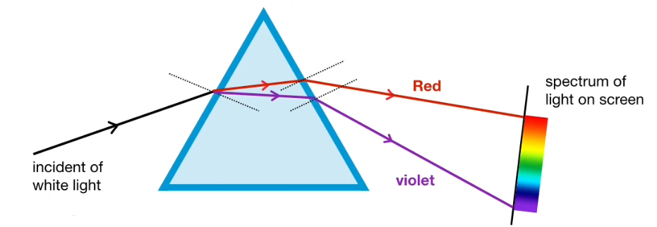
Dispersion of Light: The process where white light splits into its component colors when passing through a medium, such as a glass prism.
Refraction: The bending of light as it passes from one medium to another, causing separation of colors due to differing speeds in various wavelengths.
Visible Spectrum
Traditional Colors: The visible spectrum consists of seven colors in order of frequency and wavelength:
VIBGYOR:
Red
Orange
Yellow
Green
Blue
Indigo
Violet
Monochromatic Light: Light comprised of a single wavelength or frequency, producing only one color (e.g., laser light).
Refraction through Glass Prism
Experiment: When white light enters a triangular glass prism, it refracts at each surface, resulting in a spectrum displayed on a screen.
Behavior of Colors:
Violet: Travels slowest in glass, bent through the largest angle.
Red: Travels fastest, bent through the smallest angle.
Index of Refraction: The refractive index of glass is higher for violet light compared to red light, contributing to the degree of bending.
Electromagnetic Spectrum Context
• Visible Light Range: Human-visible light is just a small part of the electromagnetic spectrum. Animals such as birds and certain fish can see beyond this visible range, perceiving infrared and ultraviolet light.
Wavelength and Frequency
Wavelength Relationship:
Red light: Longest wavelength, lowest frequency and energy.
Violet light: Shortest wavelength, highest frequency and energy.
Why doesn’t the light ray show any change when it enters the glass block?
- Because the light ray is parallel to the normal, angle of incidence is zero, therefore angle of refraction is also zero.
Summary & Key Takeaways
Dispersion occurs when white light passes through a prism, resulting in the visible spectrum.
Refraction bends light differently based on color due to different wavelengths and speeds in glass.
Monochromatic light consists only of a single frequency, exemplified by laser beams.
Understanding the behavior of light is crucial in fields like optics and applied physics.
Key Concepts
• Electromagnetic Spectrum: A continuum of electromagnetic waves arranged by frequency and wavelength.
Major Regions of the Electromagnetic Spectrum
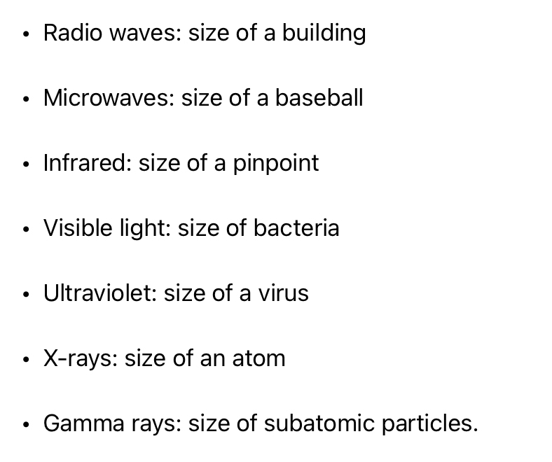
RAGING MARTIANS INVADED VENUS USNG X-RAY GUNS:
Radio waves - longest wavelength - lowest frequency- least energy
Microwaves
Infrared
Visible light
Ultraviolet
X-rays
Gamma rays - shortest wavelength - highest frequency- greatest energy
Properties of Electromagnetic Waves
All transverse waves.
Travel at 3 x 10^8 meters per second in a vacuum.
Can travel through a vacuum and air.
Uses of Electromagnetic Waves
Radio Waves: Communication (radio, television, cellular networks), RFID.
Microwaves: Satellite communication, cooking food, radar systems.
Infrared: Remote controls, thermal imaging, cooking.
Visible Light: Vision, photography, optical fiber data transmission.
Ultraviolet: Sterilization, security markings, tanning.
X-Rays: Medical imaging, security scanning.
Gamma Rays: Cancer treatment, sterilization of medical equipment.
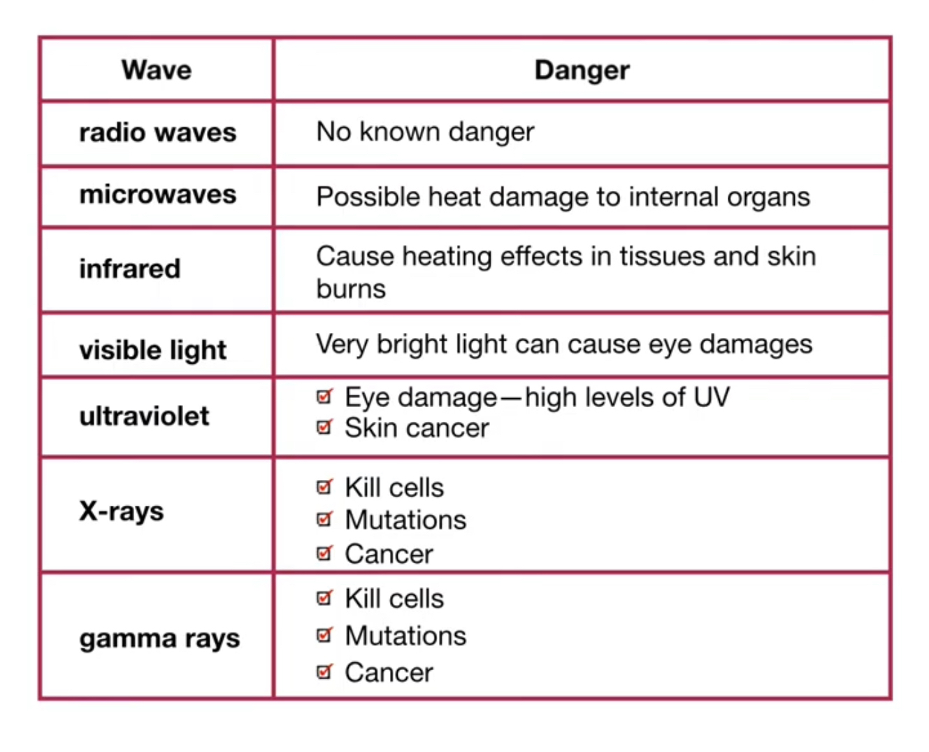
Harmful Effects of Electromagnetic Waves
Higher frequency waves can be ionizing, leading to cellular damage and cancer (e.g., UV, X-rays, gamma rays).
Lower frequency waves generally less harmful but can still cause issues with high exposure (e.g., microwaves can cause internal heating).
Communication Systems
Geostationary Satellites: Maintain a fixed position, useful for broadcasting at high altitudes (36,000 km).
Polar Satellites: Operate at lower altitudes (200 km), beneficial for monitoring and imagery with less signal delay.
Digital vs. Analog Signals:
Analog Signals: Continuous values, prone to noise (e.g., older broadcasting methods).
Digital Signals: Discrete values (Os and 1s), less noisy, and allow for error-checking and regeneration.
Summary & Key Takeaways
Understanding the electromagnetic spectrum is essential for grasping communication technologies.
Higher frequency waves pose greater risks due to ionization potential.
Digital signals provide significant advantages in data transmission over analog signals.
Protective measures should be taken to mitigate the harmful effects of higher frequency electromagnetic waves.
Properties of Sound
Sound Production and Characteristics
Vibrating Sources: Sound is produced by vibrating objects, creating longitudinal waves characterized by compressions (high pressure) and rarefactions (low pressure).
Sound Transmission: Sound requires a medium (air, water, solids) for transmission; it cannot travel through a vacuum.
Speed of Sound
• Speed in Different Mediums:
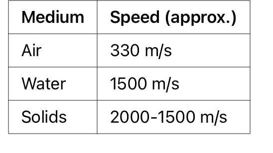
Frequency and Human Hearing
Audible Frequency Range: Humans can hear frequencies between 20 Hz and 20,000 Hz.
Frequencies above this range are termed ultrasound (>20,000 Hz), while those below 20 Hz are termed infrasound.FPAL - FREQUENCY, PITCH - AMPLITUDE, LOUDNESS
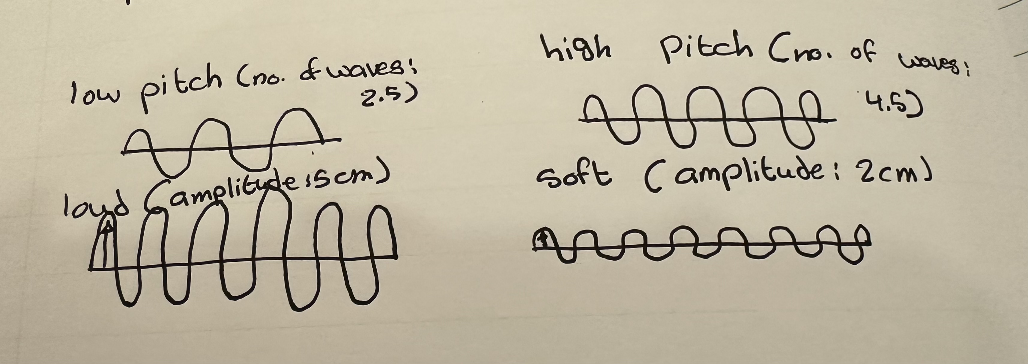
Pitch and Amplitude:
Pitch: Determined by frequency; lower frequencies produce lower pitches and longer wavelengths, while higher frequencies produce higher pitches and shorter wavelengths.
Loudness: Related to amplitude; larger amplitudes yield louder sounds, whereas smaller amplitudes produce quieter sounds.
Experimental Methods for Determining Speed of Sound
Measurement Techniques
1. Distance and Time Method:
Two people (100 meters apart), one bangs blocks, and the other uses a stopwatch to measure the time between seeing and hearing the sound.
Speed calculation: Speed = Distance / Time.
2. Echo Method:
• A person claps blocks near a wall (50 meters away) and times the interval until the echo is heard.
Calculation: Speed is computed from Speed = 2 * Distance / Echo Time.
Sound Wave Diffraction
• Sound can diffract around corners and through gaps because its wavelength is comparable to the size of obstacles, allowing it to be heard around barriers (e.g., buildings).
Applications of Ultrasound
Sonar: Used for navigation and object detection underwater.
Echo sounding measures depth via time taken for reflected sound waves.
Medical Imaging: Constructs images of soft tissues (e.g., fetal imaging) and detects internal structures.
Non-Destructive Testing: Identifies defects in materials by reflecting sound waves; variations in return times indicate flaws.