uno (copy)
Structural Properties (Structural requirements)
4 properties a structure must possess to perform its function of supporting a building in response to whatever loads may be applied to it:
Equilibrium: Structure must balance all applied loads with foundation reactions.
Stability: Capability of structure to maintain its geometry and resist loads without toppling, sliding, bending, or twisting.
Strength: Structural materials must withstand acting forces.
Rigidity: Ability to retain shape under load.
Selecting Suitable Foundation Based on Soil Condition
Shallow Foundations: Suitable when surface soil can support loads.
Deep Foundations: Necessary when deep hard strata are required for support, especially under high load conditions like multi-storey buildings.
Step foundations: recommended for uneven ground levels.
Load Considerations for Foundation Selection
Shallow foundations recommended for low-rise buildings.
Deep foundations required for high-rise buildings with concentrated loads.
Use of pads and piles common in framed structures with concentrated loads, while piles are unnecessary for uniformly distributed loads.
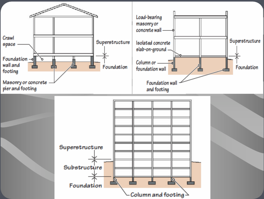
Definition and Functions of Foundation
Foundation: Supports loads from columns, beams, slabs.
Functions:
Prevent settlement and differential settlement.
Resist movement from soil swelling/shrinkage.
Allows construction over unstable land.
Resists uplifting and lateral forces.
Resist lateral forces due to soil movement.
Underpins (support) existing unstable structures.
Foundation Elements
Load-bearing masonry/concrete walls and foundation details.
Factors Influencing Foundation Performance
Soil nature: Determines load capacity.
Materials: Influences durability and cost.
Economic considerations: Budget impacts material choices.
Layout: Building/floor plan, positioning loads, etc. affect loading distribution.
Site conditions: Space for construction matters. (Location and sufficient work space)
Page 10
Foundation Loads
Types of loads supported by foundations:
Dead Loads: Weight of the structure itself/building. (Including walls, floors, and roofs, that are constant over time.)
Live Loads: Weight from occupants, furniture, equipment they use, etc.
Wind Loads: Lateral, downward, and uplift forces due to wind.
Earth & Water Pressures: Forces from soil and water against basement walls.
Horizontal Thrusts: From arches, rigid frames, domes, vaults, or tensile structures
Buoyant Uplift Forces: Forces from underground water. (Identical to forces that make boats float)
Ground forces: Horizontal and vertical forces caused by the motion of the ground relative to the building.
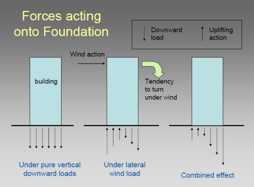
Forces Acting on Foundation
Downward and uplift loads.
Wind-induced lateral forces.
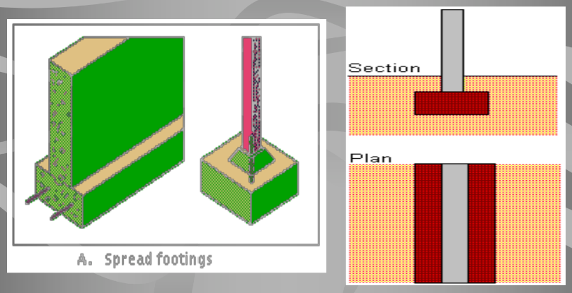
Difference between Foundation and Footing
Foundation: The entire below-grade structure responsible for transmitting loads to the soil (Carries the load into the ground)
Footing: A specific enlarged section (widened parts) under walls or columns at bases designed to reduce soil pressure and ensure stability across a larger area.
Types of Foundation
Shallow Foundation: Extends short distance below ground.
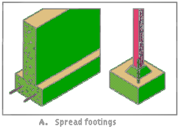
Spread Foundation: Often referred to as a footer, this enlarges at the bottom of columns or walls to effectively distribute loads over a greater soil area.
Mat/Raft Foundation: A large continuous footing that bears the entire structure load, ideal in cases where soil bearing capacity is limited.
Deep Foundation: Used when surface soil is weak.
Pile
Diaphragm Wall
Pile Wall
Caissons
Advantages of Shallow Foundation
Cost-efficient.
Simple construction process.
Primarily uses concrete.
Requires less skilled labor.
Spread Footing Foundation
Also called footer or footing.
Enlarges at the bottom of columns/walls to distribute loads over larger soil area.
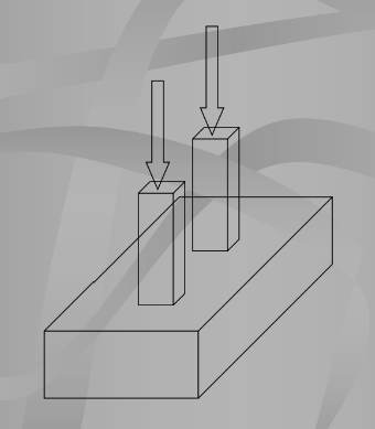
Each column & each bearing wall has its own spread footing.
Each structure may include dozens of individual footings.
Foundation Configurations
Description of various foundation setups and structural relationships.
Foundation consists of concrete slabs located under each structural column and a continuous slab under load-bearing walls.
Spread foundation System: Structural load is literally spread out over a broad area under the building
Most common type of foundation used due to their low cost & ease of construction
Common in small to medium structures with good soil conditions.
Shapes and Sizes of Spread Footings
Various forms:
Square
Rectangular
Circular
Continuous
Combined
Ring footings
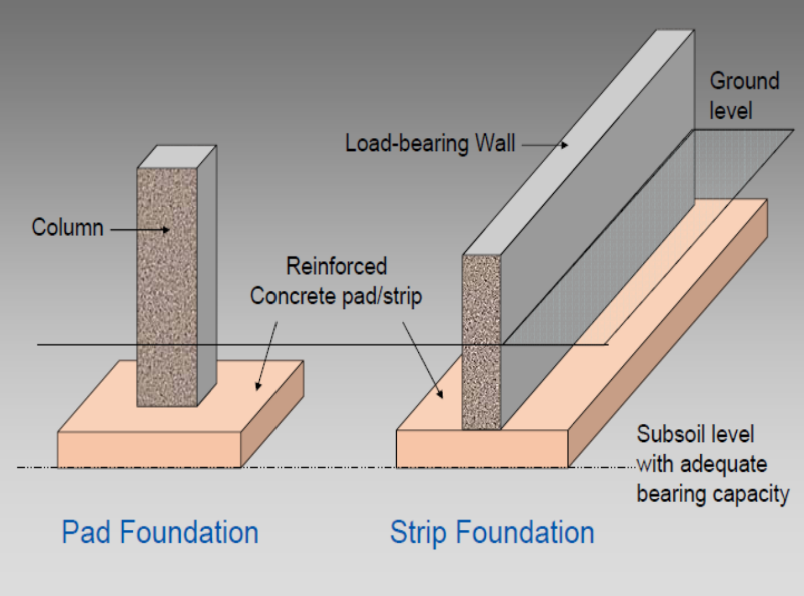
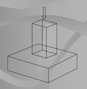
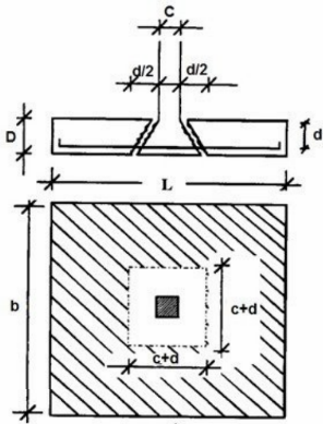
Square Spread Footings/Pad Foundation
Support single centrally located columns.
Concrete ratio is 1:2:4
Reinforcement in both axes are installed to resist/carry tension loads
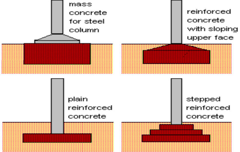
Pad Foundation
Mass concrete details and design for strength.
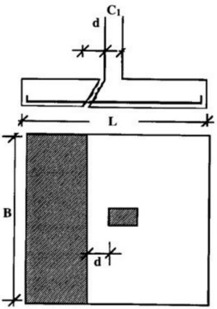
Rectangular Spread Footings
Recommended when obstructions hinder square footings with a sufficiently large base area and when large moment loads are present.
Circular Spread Footings
Round in plan view
Typically used for light structures. (flagpoles and power transmission lines)
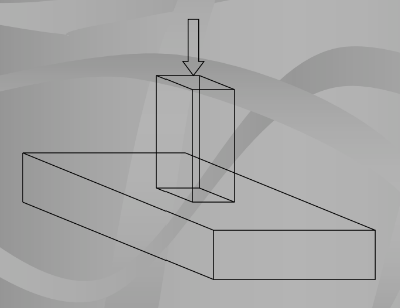
Continuous Spread Footings/Strip Foundation
Used to support bearing walls
Combined Footings
Support multiple columns close together.
columns too close together to have separate footing.
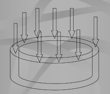
Ring Spread Footings
Continuous footings that have been wrapped into a circle.
Specially designated to support the walls above-ground circular storage tanks.
Engineered to handle the uniform load distributed around the circular base effectively.
Spread evenly across the total base area and this weight is probably greater that the tank itself.
Circular foundation with diameters equal to the diameter of the tank
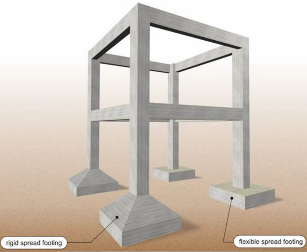
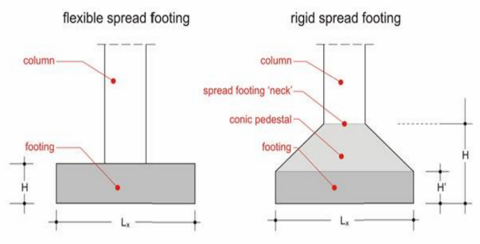
Foundation Types: Flexible vs. Rigid Spread Footings
Differences in structural integration and use cases.
Page 29
Footing Dimensions
Determined by soil quality and loading conditions transferred by the columns
Column Loads: Determined by the distance between the columns along with the number and loads of the structure’s storeys
Typical dimensions (in meters) range from 1.0 × 1.0 to 3.0 × 3.0
maybe larger sometimes and height varies between 0.5 and 1.0 (flexible spread footings) and between 0.7 and 2.0 (rigid spread footings)
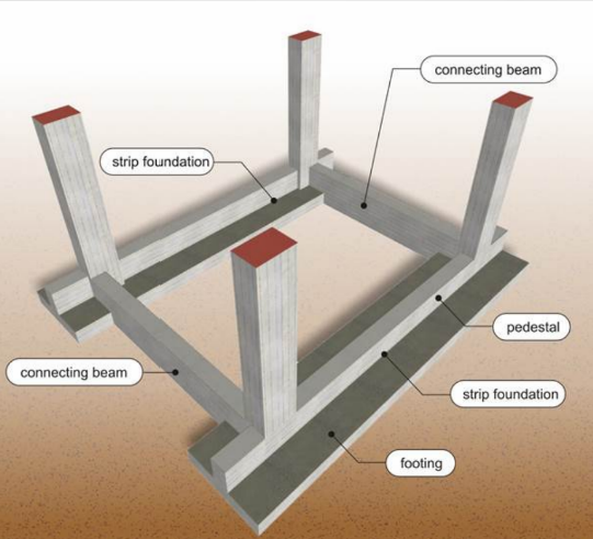
Foundation Configuration with Connecting Beams
Importance of design to ensure stability under various conditions.
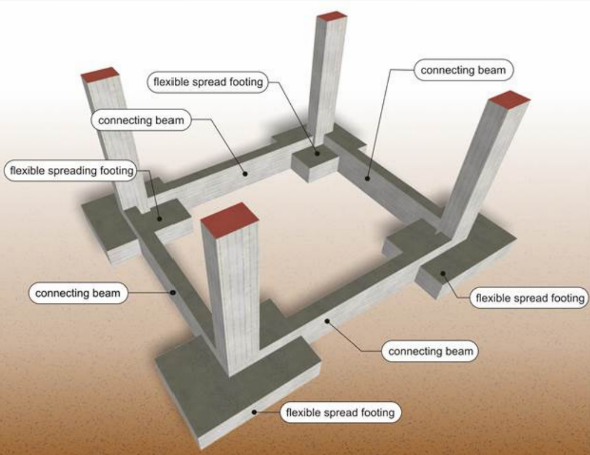
Connecting Beams Criteria
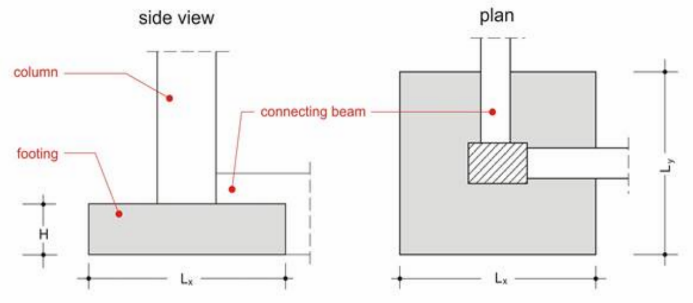
Use of foundation beams (connecting beams) is mandatory to ensure the proper behavior of the foundation
These beams tie together the column’s bases making the footings behave in a even way especially during seismic incidents
Cross section width (in mm) usually ranges from 300 and 500
Cross section height (in mm) usually ranges from 500 to 1500
Footings: constructed symmetrically to their mass center
eccentrically constructed in cases when there are building restrictions (boundaries of the building line or edge of the building land).
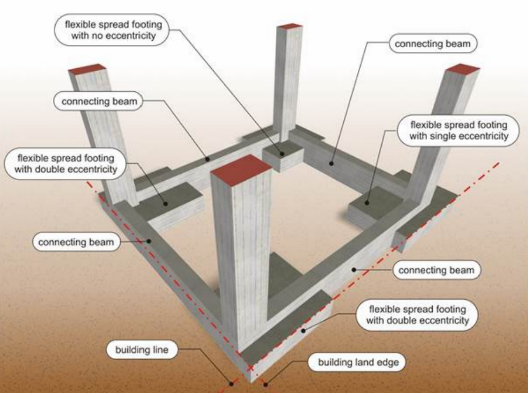
Higher footing construction eccentricity = the strongest must be the connecting beam in that direction should be
Spread Foundation (Pad Foundation): used in a good quality soil
In case of low soil capacity, strip foundation is used
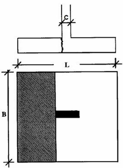
Strip Foundation
An inverted T beam
consists of web and the flange (footing)
Usual dimensions (in mm)
Thickness: vary between 400 to 600
Width: 1000 to 2500
Typical web cross section: 300×800 to 500×1500
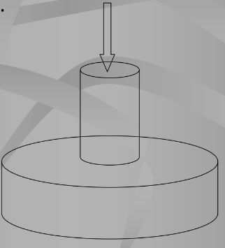
Spread Footing Concept
To uniformly distribute and disperse concentrated loads from above to prevent exceeding the ground's allowable bearing capacity.
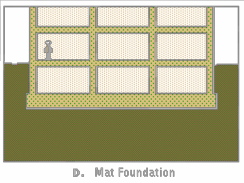
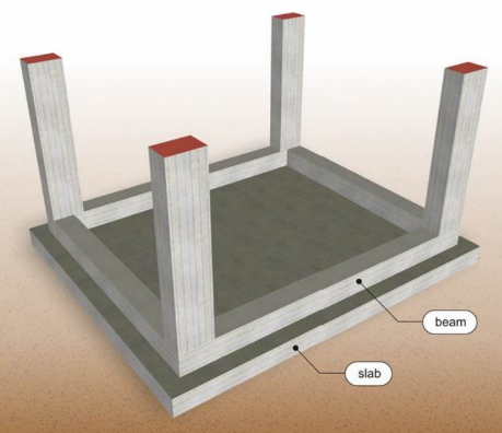
Mat/Raft Foundation
Where the entire building is on a large continuous footing, typically a flat concrete slab heavily reinforced with steel that carries the loads of individual columns or walls.
Purpose: Spreads the load from a structure over a large area, generally the entire footprint of the structure.
A mat foundation consists of a single thick, reinforced slab.
Types of Mat Foundations
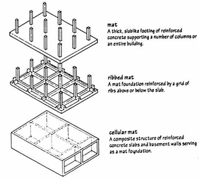
Mat Foundation
A thick concrete slab supporting multiple columns or an entire building.
Ribbed Mat
A reinforced mat foundation with grids of ribs above or below the slab.
Cellular Mat
A composite structure of reinforced concrete slabs and basement walls acts as a mat foundation.
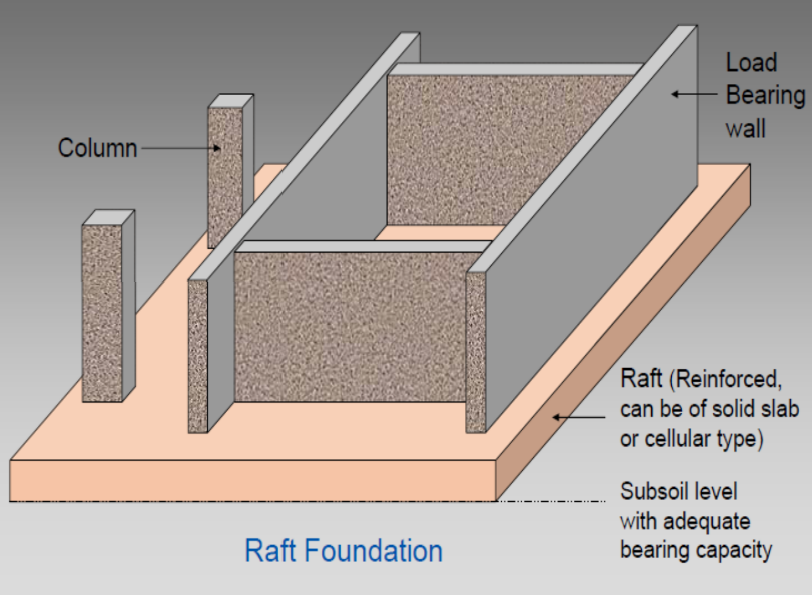
Components of Raft Foundation
Load Bearing Wall
Column
Raft (Reinforced, can be a solid slab or cellular type)
Subsoil level must have adequate bearing capacity for the raft foundation.
Raft Foundation with Connecting Beams
In poor soil conditions, raft foundations, which extend over the entire loaded area, are preferable for ease of construction.
Features:
Can have regular foundation beams as ribs.
May include hidden beams embedded in the foundation.
Typical thickness (in mm): 400 to 1000
Beam dimensions (in mm) range from 300x800 to 500x2000
Advantages of Raft Foundations
Consists of a concrete slab over the entire loaded area, stiffened by ribs or beams.
Reduces differential settlements by resisting movements between loading positions.
Ideal on soft or loose soils with low bearing capacity to spread loads.
When to Use Mat Foundation
High structural loads or poor soil conditions necessitate large spread footings (>50% of the footprint area).
Erratic soil prone to differential settlements.
Erratic structural loads that lead to excessive settlements.
Lateral loads are not uniformly distributed through the structure.
Uplift loads area larger than spread footings can accommodate.
Bottom of the structure is located below the groundwater table (waterproofing is an important concern)
Mats are monolithic: easier to waterproof
Weight also helps resist hydrostatic uplift forces from the groundwater
Conditions Favoring Mat Foundation
High structural loads or soil conditions are so poor that spread footings would be exceptionally large.
General rule of thumb: If spread footings would cover more than 50% of the building footprint area, a mat or some type of deep foundation will usually be more economical.
Continuity and flexural strength of the mat help bridge irregularities in the soil
Useful on expansive soils prone to differential heaves. (Soil is very erratic & prone to excessive differential settlements)
Resistance to non-uniform lateral loads causing horizontal movements in spread footings and pile caps. (Lateral loads are not uniformly distributed)
Uplift loads are larger than spread footings can accommodate.
Bottom of the structure is located below the groundwater table (Waterproofing concerns)
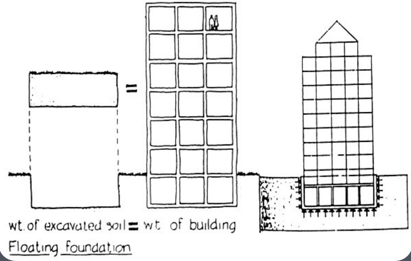
Floating Foundations
Concept: Balances the weight of excavated soil with the weight of the building to prevent harmful subsidence without stressing the ground beneath.
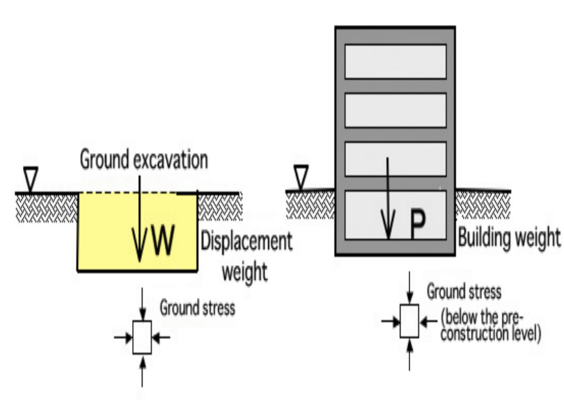
Ground and Building Weight Balance
Ground stress comparisons before and after construction.
Purpose of Floating Foundations
Prevent subsidence by balancing loads, particularly in soft ground conditions or for buildings with basement levels.
Subsidence: motion of the surface (usually earth’s surface) as it shifts downward relative to a datum (ex. sea level)
Uplift: opposite of subsidence; results in an increase in elevation
Achieved by balancing building load and the load of soil displaced during excavations
Comparable to piled foundations (particularly under conditions of soft ground or buildings with basement levels)
Deep Foundations Overview
Deep Foundation: Extends several meters below the building.
Types:
Piles
Piers
Caissons
Compensated Foundations
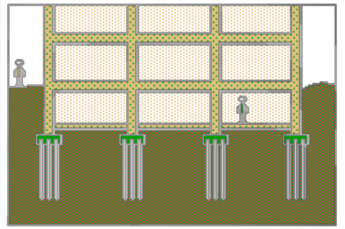
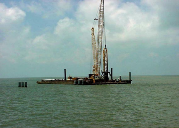
Piles
Slender structural members made of steel, concrete, or timber, installed to transfer loads to deeper soil layers.
Situations for Pile Foundation Use
Soil near the surface lacks sufficient bearing capacity.
Estimated soil settlement exceeds tolerable limits.
Excessive differential settlement expected.
Difficult excavation conditions for shallow foundations.
Load Transfer by Piles
1. End Bearing Piles
Transmit loads to firm soil layers like rock or dense sand.
2 types: Preformed Timber Pile and In-situ Reinforced Concrete Pile
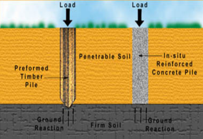
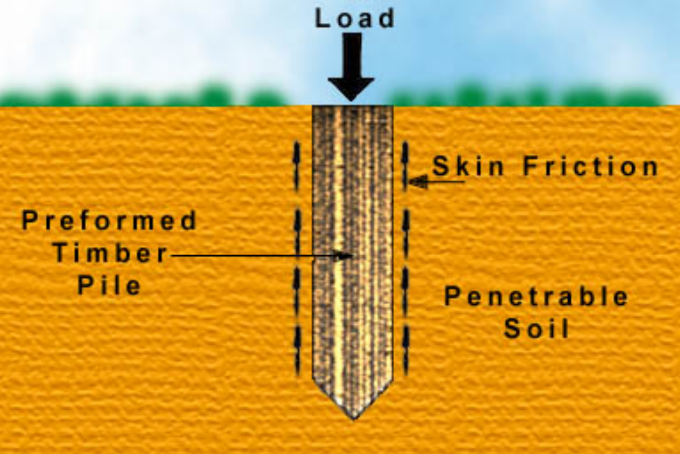
2. Friction Piles
Transfer loads through skin friction between the soil and pile surface.
May be used to support downward load
Types of Piles
Concrete Piles:
Cast-In-Place Concrete Piles
Precast Concrete Piles
Drilled Shafts
Steel Piles:
H-Piles
Cylindrical
Tapered
Timber Piles
Composite Piles
Cast-in-Place Concrete Piles
Created by driving a cylindrical steel shell into the ground, which is then filled with concrete.
Steel shell functions as formwork and doesn't contribute to load transfer.
Requires vigilant quality control for integrity.
Advantages of Cast-in-Place Concrete Piles
Can withstand hard driving.
Resistant to marine organisms.
Easily inspected.
Length adjustable.
Easy to handle.
Precast Concrete Piles
Typically square, circular, or octagonal in cross-section.
Fabricated from reinforced or pre-stressed concrete in a yard.
Challenges include transport and length adjustments.
Higher capacity than timber piles.
Steel Piles
Available in various shapes and sizes.
Steel H-Piles are rolled sections.
Steel pipe piles can be welded, yielding lengths of up to 70m.
Usually driven with open ends into the soil.
Use conical tips for penetration in rocky soil; pre-treatment for corrosive conditions may be necessary.
Timber Piles
Traditionally used (ancient(
Length depends on harvested tree types.
Typical length around 12m.
Vulnerable to pests and decay
Lower capacity and unsuitable for hard driving, but cheaper.
Factors Influencing Pile Selection
Availability of pile type.
Location and structural loading magnitude.
Ground conditions (soil type).
Cost
Durability of materials.
Types of Pile Construction
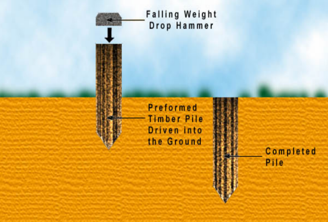
Displacement Piles (Driven)
Displace soil radially and vertically during insertion.
Finished product using preformed timber pile driven into the ground employing drop hammer techniques.
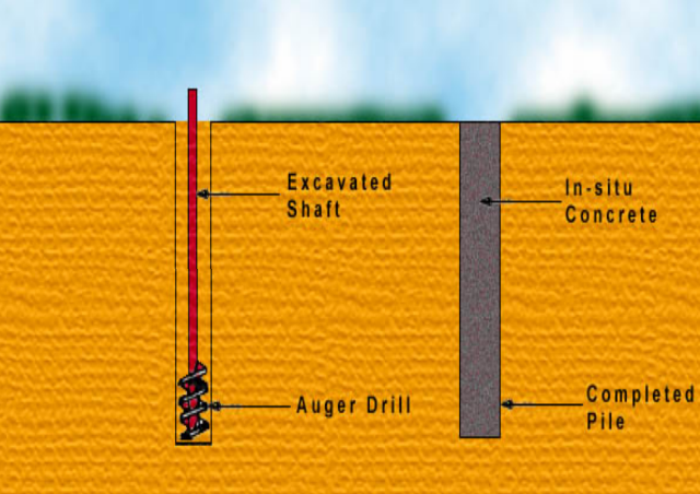
Non-Displacement Piles (Bored)
Remove soil and fill with concrete or drop pre-cast piles into the hole.
Excavated in-situ shaft using auger drills to create non-displacement piles.
Types of Displacement Piles
Can be classified based on how they are constructed and inserted
Totally Preformed Displacement Piles (Precast Concrete or Steel Pile)
Precast concrete or steel types.
Driven & Cast-In-Place Displacement Pile
Driven Piles: These are displacement piles that are driven into the ground, which displaces soil radially and vertically during insertion.
Cast-In-Place Piles: These are non-displacement piles where soil is removed and replaced with concrete, such as drilled shafts.
Helical Cast-In-Place Displacement Piles
Constructed with a special auger which compacts the soil instead of removing it.
auger is carried on a hollow stem which can be filled with concrete, so when the required depth has been reached concrete can be pumped down the stem & the auger slowly unscrewed leaving the pile cast in place
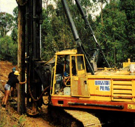
Method of Displacement Pile Installation
Different methods including drop hammers, diesel hammers, vibratory methods, and jacking for pile insertion.
Dropping Weight or Drop Hammers:
Involves raising and releasing weight on the pile head; commonly used.
Diesel Hammers:
suitable to drive pile in non cohesive granular soil
Vibratory Hammers:
Effective for non-cohesive granular soils; reduces friction.
Jacking Method:
Commonly used in underpinning.
Diesel Hammer
Rapid controlled explosions can be produced by the diesel hammer.
Explosions raise a ram that drives the pile into the ground.
Despite being smaller than the weight in drop hammers, increased strike frequency compensates for inefficiency.
Most suitable for driving piles through non-cohesive granular soils, with resistance primarily from end bearing.
Vibratory Method of Pile Driving
Vibratory methods effectively drive piles through non-cohesive granular soils.
Vibration causes soil grains adjacent to the pile to behave like a fluid, reducing friction along the pile shaft.
Concerns include potential damage to equipment and the risk of noise and vibration-induced settlement in nearby buildings.
Pile Driving Rig
A structure that raises and temporarily supports the pile during the driving process, as well as supports the pile hammer.
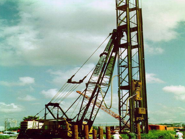
Dropping Weight / Drop Hammers
A weight around half the pile weight is raised to a suitable height and released to strike the pile head.
For hollow pile tubes, weight acts on a plug at the bottom, minimizing stress along the pile length during insertion.
Pile installation using drop hammer
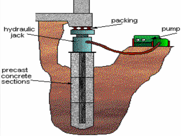
Jacking Method of Insertion
Commonly used for underpinning structures.
Short lengths of pile can be inserted and jacked into the ground using the existing structure as a reaction.
Non-Displacement Piles
Four types:
Small Diameter Cast-In-Place
Large Diameter Cast-In-Place
Partially Preformed Piles
Grout or Concrete Intruded Piles
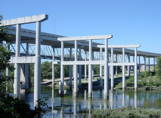
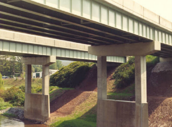
Piers
Vertical bridge supports.
Foundations designed to carry heavy structural loads constructed on-site in deep excavations.

Construction Considerations for Piers
Drilling through wet or caving soils may require temporary steel casing, tremie, and pump for dewatering and concrete placement.
Reinforcement challenges at full depth due to difficulty in getting bars with proper cover; use centralized placement and larger diameter bars.
Don’t leave holes open for any length of time even in dry conditions (have concrete on site and fill right after drilling and cleaning).
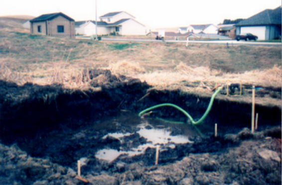
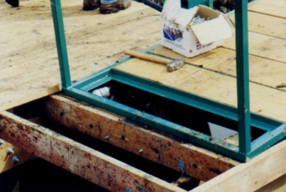
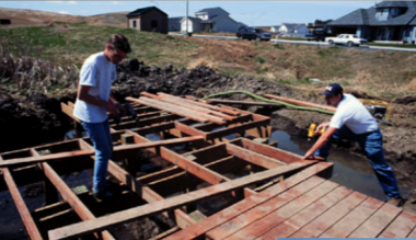
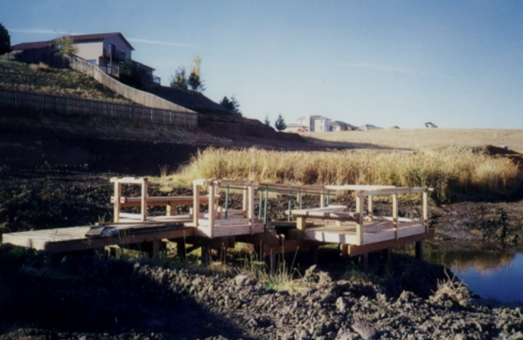
Pier Construction
Pumping water out of the hole for the excavation of the pier
Construction of pier framing
Completed pier framing
Post-footing and detail
Installation of ramp
Bolting of ramp
Floor decking installation
Completed Pier
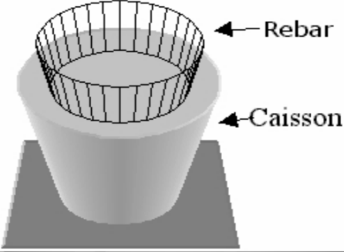
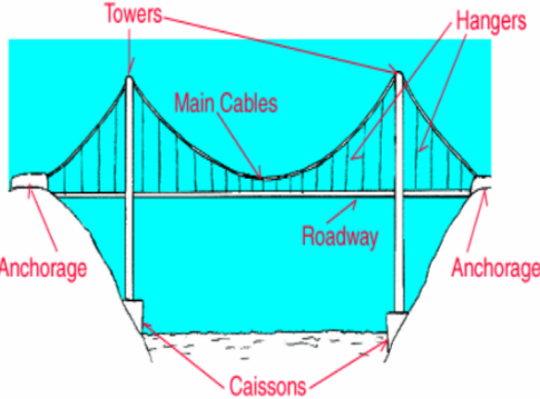
Page 21: Caisson Foundation
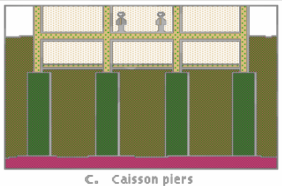
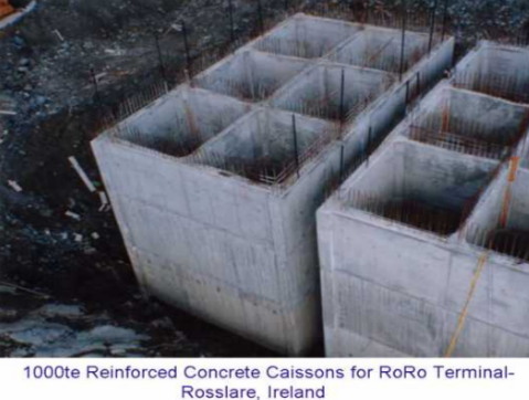
A caisson is a prefabricated hollow box or cylinder sunk into the ground and filled with concrete, forming a foundation.
Most commonly used for bridge piers and structures needing foundations beneath water bodies.
Similar to pile foundations but installed differently and used where stable soil is found beneath weaker materials.
It's a deep foundation type constructed above ground and then sunk by excavating or dredging.
Construction of Caisson Foundation
Consists of concrete columns in cylindrical shafts excavated at structural column locations.
Caissons are drilled down to bedrock or suitable deep strata to support building loads.
Created by auguring a deep hole in the ground
2 or more “stick” reinforcing bar are inserted into and run the full length of the hole
Concrete is poured into the caisson hole
Caisson foundations carry the building loads at their lower ends (often bell shaped)
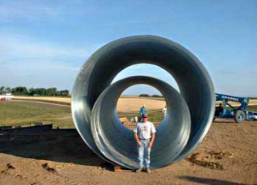
Types of Caissons
Box Caissons
Excavated Caissons
Floating Caissons
Open Caissons
Pneumatic Caissons
Sheeted Caissons
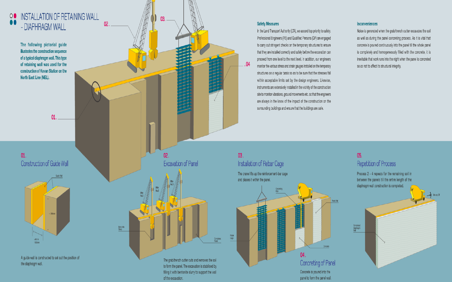
Diaphragm Wall Construction
Construction sequence includes:
Construction of guide wall.
Excavation of panel using grab/trench cutter.
Installation of rebar cage.
Concrete pour to form the wall.
Sound monitoring and vibration checks are implemented for nearby structures during construction.
Purpose of Deep Foundations
To penetrate unsuitable soil layers for adequate load resistance through:
End-bearing on stable soil or bedrock.
Frictional resistance along the foundation length.
Combination of both methods.
Footing Selection Factors
Bearing capacity of the underlying soil.
Magnitude of the column loads.
Position of the water table.
Depth of foundations of adjacent buildings
Foundation Depth Requirements
Ensure adequate bearing capacity and prevent movement from clay shrinkage/swelling.
footings are to penetrate below the zone where shrinkage and swelling due to seasonal weather changes are likely to cause appreciable (clay soils)
Located sufficiently below maximum scouring depth
Avoid locating footings in organic or unconsolidated materials (garbage).
Types of Foundation Failure
Three main failure modes:
Punching shear failure
One-way shear failure
Flexure failure
Punching Shear Failure
Known as diagonal tension failure.
Characterized by inclined cracks around the column perimeter.
One-Way Shear Failure
Defined by inclined cracks across the footing width that reach up to the column's face.
Flexure Failure
Occurs from increased bending moments causing the footing to fail.