Adjusting Indoor Thermal Conditions Notes
Adjusting Indoor Thermal Conditions
Focus: Modes of Thermal Transfer
The primary modes of thermal transfer are:
Conductance
Radiation
Factors Affecting Indoor Thermal Conditions (Brophy & Lewis, 2011)
Out of 21 factors, 6 measurable and adjustable factors influence indoor thermal conditions:
Air temperature (°C)
Radiant temperature (°C)
Air velocity (m/s)
Humidity (%)
Clothing insulation (clo or °C/W)
Metabolic heat (MET or Watts)
Four factors are influenced by designers (immediate environment).
Two factors relate to users/occupants.
User Comfort & Thermo-Regulation
User comfort is continuously regulated by the body's organs and blood circulation to maintain thermal comfort. Major impacts on user comfort come from:
Evaporation
Radiation
Convection
These can be measured and adjusted by user practices or the built environment.
Factors Affecting User Comfort
Six factors affecting user comfort:
Mean radiant temperature
Dry bulb temperature
Humidity
Air movement
Clothing
Activities (users undertake)
User and Environmental Adjustments
Users can adjust clothing and activities.
The local climate and design decisions affect mean radiant temperature, temperature, humidity, and air movement.
Refer to the microclimates lecture for adjustable aspects.
Mechanisms of Thermal Transmission
Three modes of thermal transfer:
Conduction
Convection
Radiation
Humans are affected by all three, but primarily by radiation (heat loss or gain).
All three mechanisms play important roles within the built environment, requiring different control tactics.
Conductance
Transfer of thermal energy from interactions between particles in a substance (higher energy to adjacent lower energy particles).
Primarily in solid matter, but can occur in gases and liquids in sealed conditions.
Energy transfer happens without particle movement; only thermal energy is transferred.
Always moves from high to low energy.
Energy Flow
Energy always flows from high to low thermal conditions. Conditions = Energy
If it's cool inside, energy flows inward.
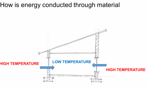
If it's hot inside (cooler outside), energy flows outward.
Factors Influencing Energy Flow
Energy flow is proportionate to:
Temperature difference (energy difference)
Area exposed
Material quality (thermal conductance or thermal transmittance)
Heat flows differently through different materials (e.g., concrete vs. timber).
Concepts for Understanding Conductance
Key concepts include:
Conductivity (K)
Thermal resistance (R)
Thermal transmittance (U)
Understanding k-values (Thermal Conductance Coefficients)
Materials behave differently when exposed to heat.
Lightweight materials with cavities propagate heat differently than solid materials (like steel beams).
K-values represent the amount of energy transferred through a specific material depth (typically 1m) per temperature difference (Kelvin).
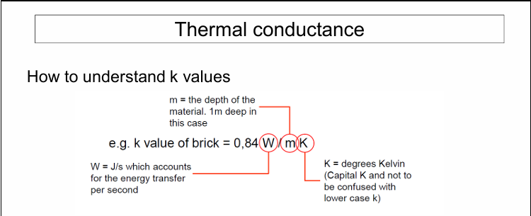
Thermal Conductance Coefficients
K-values are material-specific and can be found in schedules, product manufacturer information, or the ASHRAE fundamentals handbook.
K-values are universal for similar materials.
Thermal Conductivity (Transmittance) vs. Thermal Resistance
U-values and R-values are inverses of each other.
High R-value = low U-value
Low R-value = high U-value
A masonry wall (2,6 R) (0.38 U) with insulation will have a higher R-value than a window(0.2 R) (5.8 U).
The wall will have a lower U-value compared to the window.
(1/R)
(1/U)
Thermal Resistance (R)
Ability of a material to impede energy flow.
Thermal Resistance (R) measures how well a material stops energy from passing through it.
A higher R-value means the material is better at slowing down energy flow.
Indicates how well insulation works to keep heat inside or outside a building.
Materials with high R-values maintain comfortable indoor temperatures.
High R-values are important for energy efficiency in buildings.
High R-value = high resistance.
Thermal Conductivity (Transmittance) (U)
Ability of a material to facilitate energy flow.
Low U-value = high resistance.
Material Performance and Thermal Comfort
Different materials (e.g. different wall/roof materials) result in varying indoor thermal comfort due to differences in their R-values (thermal envelope).
Calculating Thermal Resistance
Applicable for homogenous materials.
444444444444444444444444444444444444444444444444444444444444444444444444444444444444444444444444444444444444444444444444444444444444444444444444444444444444444444444444444444444444444444444444444444444444444444444444444444444444444444444444444444444444444444444444444444
Conductivity vs. Resistivity are opposites.
Where:
R = Thermal Resistance
d = depth(in meters)
k = conductivity
r = resistivity
Surface Coefficients and Airflow Exposure
Insulative properties of the air film next to the surface need consideration during R-value calculation.
These surface coefficients vary based on adjacent spaces, the orientation of the surfaces, and their level of exposure.
Calculating Thermal Resistance of Composite Materials
Calculate the various material depths divided by the conductivity separately.
U value =
Where:
Rsi = Resistance surface inside
Rse = Resistance surface outside
hi = heat transfer coefficient inside
ho = heat transfer coefficient outside
d = depth of each material
k = conductivity of each material
Surface Heat Transfer Coefficients
Surface coefficients can be complex to calculate; therefore, pre-calculated surface heat transfer coefficients are used.
Choose a specific surface heat transfer coefficient for each condition (wall, ceiling, roof).
SANS 10400XA document provides additional surface heat transfer coefficients.
For typical vertical wall conditions:
Interior wall surface coefficient: 8.1 (use 8)
Exterior wall surface condition: 20
R-Value Calculation Example
290mm Plastered Masonry cavity wall with 50mm insulation (expanded polystyrene and 10mm plaster both sides)
SANS Standards for R-Values
R-values and U-values are critical for understanding heat flow.
SANS standards advise minimum R-values or U-values (for glazing).
Refer to SANS 10400 XA for R-value definitions of building materials.
Example calculation: Tiled roof with ceiling cavity and Gypsum plaster board (Clay roof tile – d = 20mm, k = 0,84, Gypsum board – d = 6mm, k = 0,17
Surface coefficient (downwards flow) = 6,6
Surface coefficient (outside) = 20
Roof Insulation Requirements
Thermal resistance of roofs in Tshwane must be 3.7.
Clearly, this roof does not comply and will require insulation.
Needed insulation R-value:
Determining Insulation Thickness
Choose insulation (Expanded polystyrene – k-value 0.033).
A 120mm board is needed
SANS 10400XA.2
This can be used as a resource to guide decisions related to insulation values needed in your roof construction.
Basic Simple Materials Example
220mm Masonry wall R-Value. No cavity, No plaster, Low wind conditions.
Herewith a R-value calculation example:
1/20 outdoor surface coefficient
1/8 indoor surface coefficient
dx/kx refers to the thickness of the material (in meters ) over the thermal conductance coefficient
In this case, a typical masonry wall is 220mm or 0,22m.
Read the thermal conductance coefficient from class notes or the formula sheet that has been shared with you. In this case it is 0.82. Therefore 0.22/0.82
The R-value is calculated which ultimately reflects the inverse of the U-value.
Complex calculations: Composite materials
270 masonry wall with 50mm aerolite insulations EQ3
The same approach is used in calculating the R-value of composite materials. Simply add the different material types together.
Simply use the outdoor and indoor surface heat transfer coefficients and the material characteristics of the wall elements together.
In this case the two layers of masonry walls (110mm each) and the 50mm (0.05m) insulation. This is all added together.
Similarlly to the previous calculations the inverse of the R-value is used to calculate the total U-value.
Complex Calculations: Cavity Constructions
In a typical cavity, thermal transfer is 60% radiation, 10% conductance, and 30% convection.
Insulation materials or reflective foils can be used.
Heat transfer coefficients across cavities have been developed.
Use heat transfer coefficients when calculating the impacts of using cavities.
Using Cavity Heat Transfer Coefficients
These coefficients can be used in R-value calculations.
Choose the transfer coefficient that closely reflects the type of cavity.
If placing a reflective surface (e.g., aluminum foil) on one or both sides, multiply the transfer coefficient by the specific coefficient.
Example: 50mm cavity heat transfer coefficient = 5.7 W/m2K. With a reflective surface, the coefficient becomes .
Complex calculations: Cavity Construction
270 masonry wall with 50mm cavity EQ3
Also, note that the same material quality as previously is used for the masonry wall (110mm) 0.11/0.82.
Finally, the cavity heat transfer coefficient (hc) is 1/5.7
Simply add the different components together to get the final R-value.
Note the U-value is again the inverse of the R-Value.
Importance of Conductance
Thermal envelope
R-value
Thermal insulation
Temperature differences
While conductance is important to consider, thermal radiation is of similar importance.
Radiation
All matter radiates thermal energy if its temperature is above 0 Kelvin (-273°C).
Most objects around us exert very low quantities of thermal energy.
Electromagnetic Radiation
All matter emits electromagnetic radiation because particles constantly move due to magnetic and electrical fields between atoms.
Energy is propagated perpendicular to the object.
Kelvin is the basic measure for the presence of thermal energy.
Forms of Radiation
Multiple forms of radiation exist around us.
From longwave radiation (imperceptible) to light (sunlight, lamps).
High forms of radiation (gamma rays) have intense energy and can be harmful.
Radiation Frequency
Frequency presents the speeds at which a certain action is taking place (rhythm, light, atom movement).
Presented as sine frequencies (trough and hill).
Range of Radiation Forms
Some radiation forms are difficult to detect.
As frequency increases, we experience heat (microwaves and infrared waves).
Further increase leads to perceptible light (700-400 nanometers).
Even higher frequency leads to ultraviolet rays (UV rays), X-rays, and gamma rays.
Clarifying Frequency and Heat
Example: A lighter.
Hottest part of the flame burns violet and blue.
As the flame cools, the color changes to yellow, orange, and red.
Heat is still experienced next to the flame, but with less thermal energy.
Speed of Light
Light travels at approximately .
C = Speed of light
f = Frequency (Hertz)
= Lambda = Wavelength
To know how fast a form of radiation travels, one would have to know:
the wave length
frequency per second
Simplified Understanding of the Speed of Light
If light speed is understood as 1:
If frequency is 1, wavelength is 1.
If frequency is 2, wavelength is 0.5.
The speed of light remains constant.
Wien’s Displacement Law
Willem Wien formulated that you can quantify the wavelength by dividing the Wien's constant (2897) with the temperature of the radiant body.
= micrometers
T = temperature (Kelvin)
Solar Radiation vs. Asteroid Radiation
Comparing solar radiation and radiation from an asteroid:
Dividing their respective temperatures in Kelvin into Weins constant (2897)
Sunlight falls within the 400-700 nanometer range (can be seen).
Asteroid falls below the infrared and shortwave range (imperceptible).
This difference is due to the thermal energy present in the bodies.
Shortwave vs. Longwave Radiation
Key differences:
Longwave radiation: mostly invisible.
Shortwave radiation (400-700nm): visible.
Shorter wavelength = higher temperature.
Shortwaves are hot and can be damaging.
Longwave radiation: emitted by all objects, cooler than shortwave radiation.
Brick wall example: absorbs shortwave radiation during the day, radiates longwave radiation at night.
Materials differ in how they reflect or absorb radiation.
Transparent materials (glass):Allow shortwave radiation through but trap longwave radiation (greenhouse effect).
Responding to Radiation
Decide to absorb or reflect radiation based on context, building type, climate, and program.
Reflection and Absorption
Materials and surfaces respond differently to radiation due to color and texture.
Silver materials reflect more radiation than black surfaces.
Smooth, polished surfaces reflect more radiation than rough surfaces (even if the same color).
Material choice affects energy absorbed or reflected.
Color and surface affect the ability of a surface to absorb or radiate thermal energy.
Key Definitions
Emissivity: Ratio of energy radiated by a surface relative to a black body at the same temperature.
Absorptivity: Fraction of incident radiation absorbed by a surface.
Reflectivity: Fraction of incident radiation reflected by a surface.
Albedo Rate: Proportion of the incident light of radiation that is reflected by a surface.
Relationship Between Absorptivity and Reflectivity
Absorptivity + reflectivity = 1
A perfect absorber will be 1 and a perfect reflector will be 1.
The closest to the perfect absorber is “VantaBlack” that has an absorptivity of 0.99
All surfaces have specific absorptivity and reflectivity coefficients (ASHRAE fundamental handbook).
Reflectivity and Emissivity
White roofs have higher emissivity rates than silver/galvanized roofs, even though both are highly reflective.
Black surfaces absorb thermal energy; use with caution for exterior use.
Black surfaces are also good at emitting heat, which can cool the indoor environment.
Average Reflectivity of Materials
Example: Brick and concrete (light) 40% or 0.4
Example: Aluminium cooling sheet 25% or 0.25
Absorptivity and emissivity are similar, but not always (e.g., white wall).
Color in Practice
Use of color to improve reflectivity or absorptivity.
Typical forms of implementation are painting roofs lighter colors, changing the surface of buildings to lighter colors or choosing lighter color paving surfaces.
Example: A study in California tested different asphalt colours and its means to reflect heat.
It found that blue green and gray asphalt was up to 18°C cooler, while white was 20°C cooler than black surfaces.
Recently a number of companies have also developed cool roofs technologies, where the molecular structure of the roofing material is highly reflective regardless of the chosen color.
Cool Roof Paints
Cool roof paints have proven to lower extreme temperatures inside with up to 4 °C
In the case of uninsulated corrugated iron houses, the periods of extreme heat stress were lowered by 90%.
Reflective Foils
Highly effective in hot climates with high radiation.
Highly reflective with low absorptivity.
Low emissivity.
Does not provide insulating capacity.
Vegetation
Provides very good shading control.
Low albedo rate and low thermal absorption.
Glazing
Glass, as a transparent material performs differently from opaque surface, as it allows a portion of shortwave radiation through the surface to heat up the space beyond
Glass is defined differently from other materials in terms of its performance in radiating conditions.
First of all four aspects affect the performance of the glazing:
The Visible transmittance = refers to the amount of light within the visible range of radiation is transmitted through the glass.
Solar heat gain factor = refers to the total visible transmittance as well the secondary heat transmitted through conducted and radiation into the space.
This is the total heat transmitted through the glass plane.
This is often denoted as a factor with 1 being 100% and 0 being 0%.
U-value = refers to the insulating properties of the material. This refers to the insulative quality of the glass.
Leakage = refers more to the window frame construction and relates to the amount of air that flows through cracks of the windows. This is often measured in litres per second.
Incidence Angle.
Clear glazing transmits 80% of shortwave radiation.
8% is reflected.
12% is retained (4% radiated inward, 8% radiated outward).
Higher solar angles transmit less energy indoors and more energy is reflected through the glazing.
SHGF - 40° :0,86 vs 80°: 0,42
VT - 40° : 0,82 vs 80°: 0,39
Rb - 40° :0,08 vs 80°: 0,51
Clear Glass Properties
84% of shortwave energy penetrates as heat gain (SHGF=0.84).
Shade Coefficient: Clear: 0,84/0,84 = 1
Laminated Glass
Improves performance with PVB (polyvinyl butyr al) layers for solar control, structural strength, security, or sound control.
Heat Absorbing Glass
Achieved by sandwiching a PVB (polyvinyl butyral) layer.
The glass is laminated with a heat-absorbing BVP layer, that reflect and absorbs a large portion of the radiation.
PVB layers typically change the color of the glazing.
Higher reflective ratings result in bronze, grey and green or blue-green colors.
Reflective Glass
Provides a very high level of reflectivity.
Reflected up to 70% of the shortwave radiation.
Can cause glare for adjacent and neighboring buildings.
Double Glazing
Two layers of clear glazing with a cavity in between.
67% of solar heat gain is transmitted.
Used in colder climates as a thermal insulative measure.
Cavity can be filled with specific gasses (such as Argon) that will improve its thermal insulative properties.
The u-value of double glazing is still a lot higher than that of an insulated wall, making a typical wall a much better insulating material.
Try considering triple glazing, with an argon-filled cavity, using aluminium frames with thermal breaks to replicate the thermal properties of a well-insulated wall.
Current U-values and SHGF glazing products:
Low E glazing: low u-value (3.7 ) & good SHGF (0.71-0.4)
Solarshield: high u-value (5.8 ) & good SHGF (0.43-0.25)
Solarvue: High u-value (5.8 ) & relative SHGF (0.69-0.46)
Standard Double Glazing: low u-value (2.73 ) & relative SHGF (0.75)
Normal glazing: high u-value (7.9 ) & poor SHGF (0.84)
It is important to note to use “Low-E” (Low emissivity) glazing, which lowers the solar heat gain factor and has a reasonably good u-value.
Putting It All Together
Lightweight materials (reflecting radiation) in some climates.
Highly insulative materials to lower indoor temperature in others.
Darker materials and high thermal insulation in very cold climates.
Balance shading, low radiation, thermal mass, and insulation in temperate climates.
Conclusion
Thermal comfort
Conduction
Radiation
Further Reading
Koch-Nielsen, H. (2002) Stay cool: a design guide for the built environment in hot climates.
Manzano-agugliaro, F., Montoya, F.G., Sabio-ortega, A. & García-cruz, A. 2015. Review of bioclimatic architecture strategies for achieving thermal comfort.
Holm, D. & Viljoen, R. 1996. Primer for Energy Conscious Design.
Lengen, J. van (2008) The barefoot architect : a handbook for green building.