Network Layer: Router Architecture, Forwarding, and Routing
Fundamentals of the Network Layer
Core Purpose and Scope:
The primary objective of the network layer is to establish end-to-end communication between network hosts by transporting packets (known as datagrams) from a sending host to a receiving host across intermediate communication networks.
Network layer capabilities and protocols are implemented in every single Internet host and router without exception.
Distinction from the Transport Layer:
Transport Layer: Provides logical, process-to-process communication between software applications running on network hosts.
Network Layer: Provides host-to-host communication, directing data across multiple intermediate communication links and physical networks between end systems.
Layer Distribution Across Network Devices:
End hosts (such as workstations, laptops, mobile devices, IoT hardware, and datacenter servers) implement the complete five-layer Internet protocol stack: Application, Transport, Network, Link, and Physical.
Network switches and routers positioned within access networks, enterprise networks, datacenter backbones, and national or global Internet Service Providers (ISPs) implement only the lower three layers: Network, Link, and Physical.
Fundamental Duties of a Router:
Inspects header fields of all IP datagrams that traverse its physical interfaces.
Dynamically transfers datagrams from incoming input ports to designated outgoing output ports to move packets along an end-to-end path.
Core Functions: Routing Versus Forwarding
Forwarding (Switching):
Definition: The localized, real-time action executed by an individual router to transfer an arriving packet from an input link interface to the appropriate outgoing link interface.
Scope: Strictly local to the router.
Mechanism: Governed by the router's local forwarding table. When a packet arrives, the router examines specific header fields (such as destination IP address) and indexes them into the local forwarding table to choose the appropriate output interface port.
Routing:
Definition: The network-wide process that calculates and determines the end-to-end path or route that packets must follow as they travel from source to destination across multiple routers.
Scope: Global and distributed across the network.
Mechanism: Implemented via routing algorithms (e.g., link-state, distance-vector) that execute across routers to compute optimal routes and populate the local forwarding tables of every router along the path.
Geographic Travel Analogy:
Routing is analogous to planning an entire cross-country road trip from Mountain View, CA to Denton, TX:
Primary route via Interstate 40 through Albuquerque, NM: and .
Northern route through Salt Lake City, UT and Denver, CO: and .
Southern route passing near Tucson, AZ and El Paso, TX: and .
Forwarding is analogous to navigating a specific roadway interchange within a single city (e.g., driving through Sacramento, CA and selecting the exact highway exit ramp to transition between Interstate 80 and Business 80).
Architectural Planes: Data Plane and Control Plane
Data Plane:
Function: Directly handles per-packet operations, specifically executing the forwarding mechanism that transfers datagrams from input ports to output ports.
Implementation: Implemented entirely in specialized hardware (such as application-specific integrated circuits [ASICs] and network processors) to ensure wire-speed packet processing.
Operating Timeframe: Nanosecond () timeframe.
Control Plane:
Function: Governs network-wide routing logic, calculating end-to-end routes and determining how packets are directed among intermediate routers.
Implementation: Implemented primarily in software running on a general-purpose routing processor.
Operating Timeframe: Millisecond () timeframe, updating tables asynchronously relative to individual packet transfers.
Plane Interdependence:
Control-plane routing algorithms communicate across routers or with a centralized software-defined networking (SDN) controller to determine paths.
The control plane writes calculated paths directly into the local forwarding tables located within the hardware data plane of each individual router.

Network Layer Service Models and Best-Effort Delivery
Reflections on the Success of Best-Effort Service:
Simplicity: The sheer simplicity of the best-effort service model enabled widespread deployment, low manufacturing cost for hardware, and universal adoption across diverse physical media.
Bandwidth Over-Provisioning: Generously provisioning link capacity and transmission speeds allows network performance to remain satisfactory for most applications under normal operating conditions.
Application-Layer Intelligence: Distributed software architectures (such as client-side buffering, Content Delivery Networks [CDNs], and adaptive bitrate streaming) provide high reliability, elasticity, and cost efficiency without requiring stateful guarantees within the network core.
Router Architecture and Internal Hardware Design
Four Major Structural Components of a Router:
Routing Processor: Executes control-plane functions in software, maintains routing tables, executes routing protocols (e.g., BGP, OSPF), coordinates management tasks, and configures hardware forwarding tables.
Switching Fabric: High-speed physical interconnect that transfers packets directly from input ports to output ports.
Router Input Ports: Hardware line cards that terminate physical links, decode link-layer protocols, consult forwarding tables, and buffer arriving datagrams.
Router Output Ports: Line cards that store datagrams delivered by the switching fabric and transmit them onto the outgoing physical transmission link using appropriate link-layer protocols.
Industrial High-Performance Implementation:
The Cisco ASR 9922 family illustrates carrier-grade modular router architecture, incorporating multi-terabit switching backplanes, redundant routing engines, and high-density line cards.

Input Port Processing and Destination-Based Forwarding
Three-Stage Pipeline Architecture of an Input Port:
1. Line Termination (Physical Layer): Performs physical-layer signal reception, conversion of incoming electrical/optical signals into digital bitstreams, and clock synchronization. The modulation and demodulation occurs here.
2. Link Layer Protocol Receive (Link Layer): Implements data link protocols (e.g., Ethernet), decapsulates link frames, checks checksums for transmission errors, and extracts the encapsulated IP datagram.
3. Lookup, Forwarding, and Queueing (Network Layer):
Inspects the IP header to determine the destination output port using the local forwarding table.
Implements input port queuing when datagrams arrive faster than the switching fabric transfer rate.

Destination Address Range Partitioning:
Routers group continuous blocks of addresses into ranges, mapping each block to a physical link interface:
Range 1:
11001000 00010111 00010000 00000000through11001000 00010111 00010111 11111111Link Interface0Range 2:
11001000 00010111 00011000 00000000through11001000 00010111 00011000 11111111Link Interface1Range 3:
11001000 00010111 00011001 00000000through11001000 00010111 00011111 11111111Link Interface2Default Range: Otherwise Link Interface
3
Longest Prefix Matching Algorithm
Address Range Resolution:
When destination address blocks do not divide cleanly into powers of two, routers utilize the longest prefix match rule.
Definition: When searching for a matching forwarding table entry for a given destination address, the router selects the entry with the longest address prefix that matches the destination address bit-by-bit from left to right.
Prefix Match Configuration Table:
Prefix Entry 0:
11001000 00010111 00010*** ********( prefix match) Link Interface0Prefix Entry 1:
11001000 00010111 00011000 ********( prefix match) Link Interface1Prefix Entry 2:
11001000 00010111 00011*** ********( prefix match) Link Interface2Default Entry: Otherwise Link Interface
3
Worked Example:
Given Destination Address:
11001000 00010111 00011000 10101010Prefix Comparison:
Matches Prefix Entry 2: The leading bits (
11001000 00010111 00011) match.Matches Prefix Entry 1: The leading bits (
11001000 00010111 00011000) match.Outcome: Because Prefix Entry 1 provides a match, which is strictly longer than the match of Entry 2, the packet is forwarded out to Link Interface 1.
Switching Fabric Architectures and Performance
Switching Rate and Performance Criteria:
Switching Rate: The aggregate throughput at which packets can be transferred from input line ports to output line ports.
Line Rate Metric: Typically expressed in multiples of the input/output line transmission rate .
Non-blocking Condition: For a router with input ports and output ports, a switching fabric is classified as non-blocking if its aggregate switching capacity satisfies: .
Three Major Switching Fabric Architectures:
1. Switching via Memory:
Operation: Handled under direct CPU control in traditional computing hardware. Upon arrival, a packet triggers an interrupt, copying the datagram over the system bus into system memory. The CPU parses the header, determines the output port, and copies the datagram across the bus to the output port.
Bottleneck: Throughput is severely restricted by memory bus bandwidth because each datagram requires two bus crossings (
Historical Context: Used in first-generation Internet routers (circa 1980)

2. Switching via Bus:
Operation: Datagrams are transferred directly from input port memory to output port memory across a shared internal bus without CPU intervention.
Bottleneck: Bus contention limits throughput. Because the bus is a shared transmission medium, only one packet can traverse the bus at any single instant.
Practical Metric: The Cisco 5600 router features a internal shared bus, providing sufficient capacity for enterprise access routers.
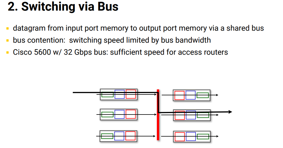
3. Switching via Interconnection Network:
Operation: Employs multi-stage 2D crossbar switches or Clos networks originally designed for parallel supercomputing. Interconnection networks route multiple non-conflicting flows concurrently across parallel paths.
Multi-stage Architecture: An fabric constructed from stages of smaller switches (e.g., multistage or crossbars).
Cell Segmentation: Variable-length IP datagrams are broken into small, fixed-length cells at the input port, switched in parallel through the fabric stages, and reassembled into the complete datagram at the output port.
Queuing Dynamics: Input Port and Output Port Buffering
Input Port Queuing and Head-of-the-Line (HOL) Blocking:
Input Queue Buildup: Occurs when the switching fabric operates at a rate slower than the aggregate arrival rate across all input ports, resulting in buffer accumulation, latency, and packet loss.
Head-of-the-Line (HOL) Blocking Definition: A condition where a datagram queued at the front of a First-In, First-Out (FIFO) input line blocks all following datagrams in the same queue, even if the destination ports and internal fabric paths for those subsequent datagrams are idle and available.
Contention Mechanism: If two input ports attempt to send packets to the same output port simultaneously, only one packet can traverse the fabric while the second is buffered at the input port, stalling any packets queued behind it.
Output Port Queuing and Buffer Exhaustion:
Cause: Arises when packets arrive from the high-speed switching fabric (at aggregate speeds up to ) faster than the outgoing line interface can transmit them ().
Buffer Policy Requirements:
Scheduling Policy: Decides which queued packet in the buffer is selected next for transmission over the outgoing link.
Drop Policy: Decides which packets are discarded when the buffer reaches maximum storage capacity.
Impact of Unlimited Buffers (Bufferbloat):
Question: Would network performance improve if routers had unlimited buffers?
Evaluation: No. Providing unlimited buffer memory harms performance by causing bufferbloat.
Technical Consequence: Rather than being dropped to signal network congestion, packets remain trapped in massive queues, introducing delays of hundreds of milliseconds or seconds. Transport protocols like TCP rely on packet drops or delay shifts to detect congestion; excessive buffering delays this feedback, leading to spurious retransmissions and degraded real-time communication.
Packet Scheduling Policies
1. First-Come, First-Served (FCFS / FIFO):
Operation: Datagrams are transmitted in the strict chronological order in which they arrive at the output queue.
Characteristics: Simple implementation in hardware; lacks traffic differentiation or quality-of-service guarantees.
2. Priority Scheduling:
Operation: Incoming traffic is classified into distinct priority tiers (e.g., high priority for real-time voice/video and low priority for bulk transfers).
Execution Rule: The scheduler always transmits packets from the highest-priority non-empty queue. Lower-priority traffic is served only when all higher-priority queues are completely empty.
Starvation: Persistent high-priority arrivals will cause complete transmission starvation for lower-priority queues.
3. Round Robin (RR) Scheduling:
Operation: Traffic is sorted into multiple logical queues by traffic class. The scheduler cyclically cycles through the classes, transmitting one complete packet from each non-empty queue per pass.
Characteristics: Guarantees fairness among classes and prevents queue starvation.
4. Weighted Fair Queuing (WFQ):
Operation: A generalized, work-conserving form of Round Robin scheduling.
Weighting Function: Each traffic class is assigned an explicit weight . In each cycle, class receives an amount of service proportional to its weight:
Bandwidth Guarantees: Both Round Robin and Weighted Fair Queuing provide quantifiable, minimum bandwidth guarantees for every active traffic class, isolating them from congestion caused by other flows.