Types of CV-joints & FWD Half Shaft Operation
Construction of a Drive Axle
FWD:
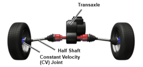
• Combines the transmission and differential
• Has a transaxle, half shaft, and CV-joint
• Has half shafts that extend to the front wheels
The CV-joint:
• Transfers equal torque to the drive wheels
• Is one of the main components of the FWD driveline
• Provides a flexible coupling
CV-joints vs. U-joints:
• Preform the same function
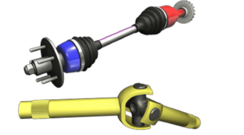
• U-joints allow the driveshaft to move with the suspension as it transfers power to the drive wheels.
• When the shaft rotates at an angle, one U-joint starts oscillation and another U-joint cancels oscillation before it reaches the Axle.
• CV-joints can work at larger operating angles.
Types of CV-joints:
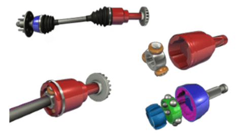
• Are categorized by location, function, and design
• Are based on:
○ Position: inboard or outboard
○ Function: fixed or plunging
○ Design: ball-type or tripod type
Inboard Joints
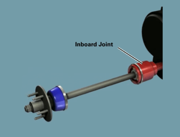
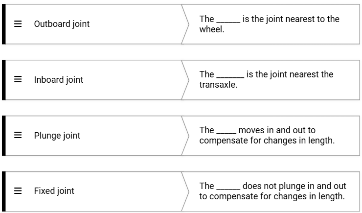
The joint near the transaxle is called the inner (inboard) joint.
The inboard joint connects to the transaxle’s differential.
The three most common types of inboard CV joints are:
Double-offset joint
Plunging tripod joint
Cross groove plunge joint
The vehicle’s make and model determine which type of CV joint is used.
Outboard Joints
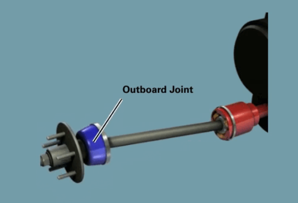
The joint near the wheels is the outer (outboard) joint.
The two most common types of outboard CV joints are:
Rzeppa joint
Fixed-tripod joint
The vehicle’s make and model determine which type of CV joint is used.
Fixed Joint
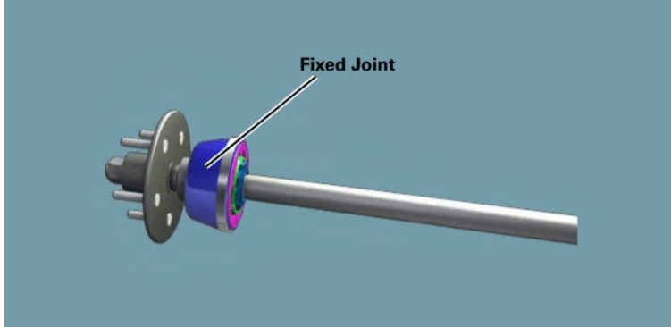
A fixed joint does not move in or out to compensate for changes in the drive axle length.
It is typically used as the outboard CV-joint on front-wheel drive vehicles.
A fixed outboard joint must allow the front wheels to turn at greater angles than a plunging joint can.
Plunging Joint
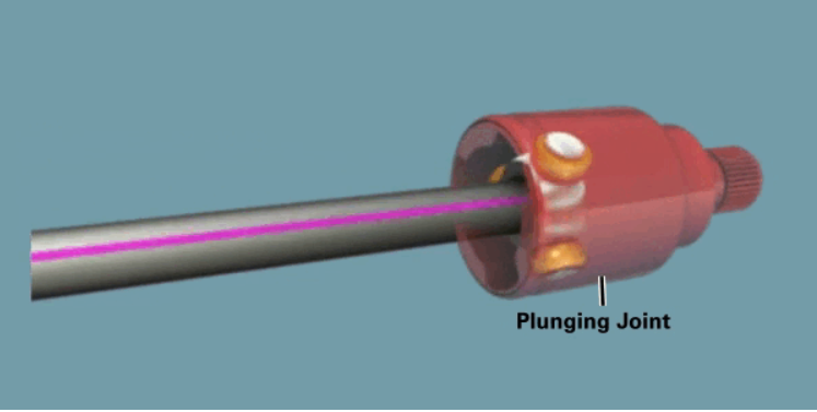
A plunging joint can move in and out to compensate for changes in axle length as the suspension moves over varying road conditions.
Inboard joints are usually plunging joints, allowing the driveshaft to slide in and out of the joint housing when the front wheels move up and down.
Types of CV-joint designs are:
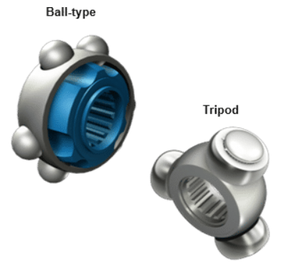
Ball-type
Tripod
Both are used as either inboard or outboard joints, as well as fixed and plunging designs.
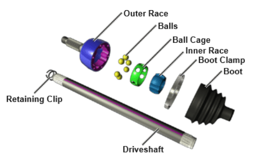
Fixed Ball-type CV-joints - Components
The components of a ball-type CV-joint include: outer race, inner race, ball cage, balls, boot clamp, boot, retaining clip, and driveshaft.
The inner race attaches to the axle and has several machined grooves around its outside diameter—one for each ball bearing.
The bearing cage holds the ball bearings in place as they move within the grooves of the inner race.
As the axle rotates, the inner race and balls rotate together, with the balls acting as bearings between the inner and outer races.
The balls transfer engine power from the inner race to the outer race while allowing smooth rotation.
Types
The Rzeppa joint is a fixed ball-type CV-joint.
The balls operate in pairs, working together to transmit power smoothly.
If one ball shows heavy wear in its groove, the paired ball will also exhibit similar wear.
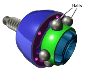
Description
The most common type of CV-joint is based on a ball-and-socket design.
This design eliminates vibration and binding issues caused by the joint’s operating angles.
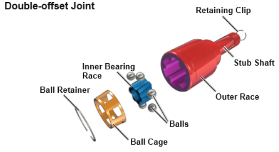
Plunging Ball-type Joints/Double-offset - Components
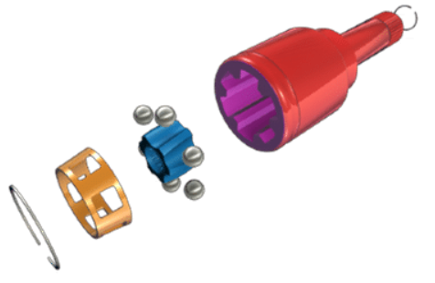
The components of a double-offset CV-joint include: ball retainer, ball cage, balls, inner bearing race, outer race, retaining clip, and stub shaft.
This joint is similar to a Rzeppa joint, except it has longer grooves machined into the inner bearing race.
Description
A Rzeppa CV-joint can be modified into a plunging joint by lengthening the ball grooves in the inner race.
This design is typically used in applications requiring higher operating angles and greater depth.
The modified version is known as the double-offset joint.
Plunging Ball-type Joints/Cross Groove CV-joint - Components
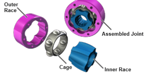
The components of the cross groove CV-joint are the cage and balls, outer race, and inner race.
Description
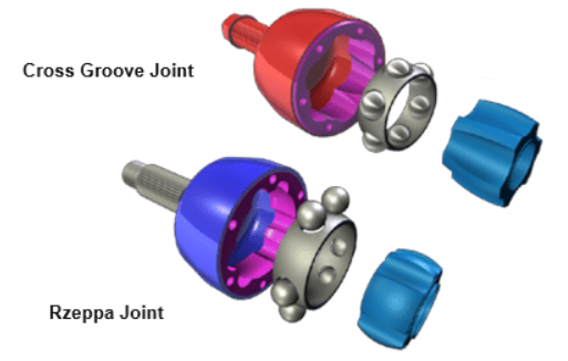
The cross groove CV-joint is similar to the Rzeppa joint, but the grooves in the races are cut at an angle.
It has a flatter design than other plunging joints.
This design allows it to handle a large amount of plunge in a short distance.
The inner and outer races share the plunging motion equally, reducing the overall depth needed for a given amount of plunge.
This type of joint is commonly found in German-made vehicles.
Tripod Plunging CV-joints - Components
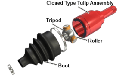
The components of a tripod plunging joint include the boot and outer housing (also called the tulip assembly).
It contains a tripod assembly with three spherical rollers that ride on needle bearings.
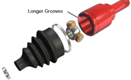
The tulip housing has three grooves, allowing the rollers to move in and out as the axle length changes.
Description
A plunging tripod joint has longer grooves in the outer housing than a fixed joint, allowing the tripod assembly to move in and out within the housing.
Some tripod joints feature a closed outer housing, while others have an open housing with machined roller tracks.
Both American and European vehicles commonly use plunging tripod-type joints.
Fixed Tripod CV-joints - Components
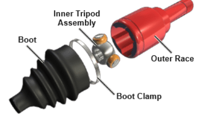
The components of the fixed tripod joints are the outer race, inner tripod assembly, boot clamp, and boot.
Description
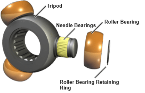
The fixed tripod CV-joint has a central hub (tripod) with three trunnions, each fitted with spherical rollers on needle bearings.
The spherical rollers ride in the grooves of the outer housing, which connects to the front wheels.
This design provides constant velocity, regardless of hub movement.
FWD Half Shaft Operation
A front-wheel drive half shaft contains two CV-joints.
The outboard CV-joint is typically a fixed joint, while the inboard CV-joint is a plunging joint.
The main components of CV-joints are the inner race, outer race, and cage.
Step 1 -
The side gear of the differential transfers torque to the outer race of the inboard CV-joint.
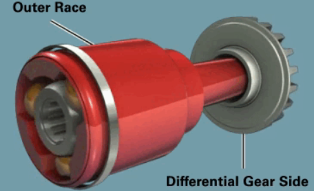
Step 2 -
The bearing transfers torque
The inner race is splined to the half shaft
Torque is transferred to the half shaft
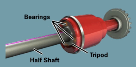
Step 3 -
The bearings transfer torque from one race to the other
Step 4 -
The half shaft transfers torque to the inner race
The inner race transfers torque to the outer race
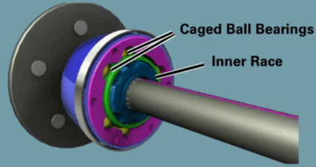
Step 5 -
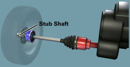
The stub shaft is built into the CV housing (outer race).
As the outer race rotates, the stub shaft rotates with it.
The stub shaft drives the hub, which in turn drives the wheels.