DLP Unit 7: Rear Axle Service
The rear axle assembly serves several important functions:
Transfers power from the transmission to the drive wheels.
Provides the final gear ratio reduction and changes the direction of power flow by 90°.
Holds the drive wheels in position while allowing them to rotate.
Adjusts the rotation speed of the wheels when the vehicle is turning a corner.
Supports suspension and brake components.
There are three types of rear axle assemblies: full-floating, semi-floating, and independent.
Each type is distinguished by its design and whether the axle shaft supports vehicle weight.
Full-Floating Rear Axle:
Axle shafts do not support the vehicle’s weight; the axle housing carries the load.
The wheel hub contains bearings that ride on the spindle of the axle housing, isolating the axle shaft from the vehicle’s weight.
The axle shaft’s sole purpose is to transfer torque to the drive wheels.
Typically used in medium and heavy-duty trucks.
Semi-Floating Rear Axle:
Supports the weight of the vehicle and drives the wheels.
The rear axle bearing is typically pressed into the axle housing and supports the axle shaft when installed.
Some models have a reluctor pressed onto the axle for wheel speed sensors.
Commonly used in light-duty trucks and rear-wheel-drive (RWD) cars.
Independent Rear Axle:
Composed of half-shafts or drive axles with U-joints.
The differential is rigidly mounted to the vehicle frame or underbody.
Axle shafts use CV-joints or U-joints at each end to provide flexibility and accommodate suspension travel.
Examples include rear drive modules (RDMs) used in many modern vehicles.
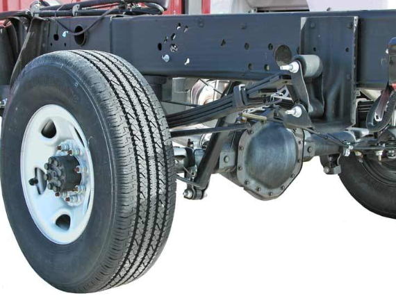
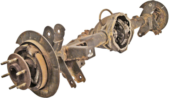
Rear Axle Assembly Housing
The rear axle assembly encloses all its components within the housing, which also serves as a mounting point for suspension and braking components.
Even minor issues within the rear axle can negatively affect performance, handling, and safety, and may cause noise or vibrations that concern customers.
Integral Carrier Housing:
In an integral carrier axle housing, the pinion with bearings and the differential with bearings are all supported by the axle housing in a single casting.
Internal components can be accessed for repair or replacement through a rear cover.
Rear covers are sealed with a gasket or RTV (room temperature vulcanizing) sealant—always follow manufacturer specifications.
Non-Integral (Removable) Carrier Housing:
A non-integral or removable carrier is detachable from the axle housing as a complete assembly.
The differential mounts on two opposing tapered roller bearings retained in the removable housing, allowing it to be removed as one piece.
Non-integral carriers are often called the third member, dropout carrier, or pumpkin.
Key Points:
Both integral and non-integral rear axle housings are similar in appearance.
On a non-integral carrier, the opening for the differential is at the front, while the rear of the housing is solid.
The rear axle housing is sometimes called a banjo due to the bulge in the center, which houses the differential and final drive gears.
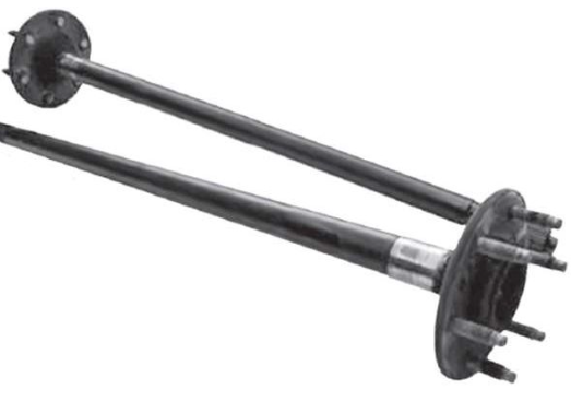
Axle Shafts
The axle shaft transmits rotational torque from the differential axle side gears to the drive wheels.
Axle shafts (or drive axles) are located inside the hollow tubes of the axle housing and are made of solid metal.
The splines on one end of the axle shaft mesh with the differential side gears inside the differential.
Semi-Floating Axle Shaft:
The opposite end is flanged with wheel studs to hold the wheel.
Retention in the axle housing is by a C-clip in the differential side gear or a flange and collet pressed onto the axle.
Full-Floating Axle Shaft:
The opposite end is a flanged end that bolts to the wheel hub, driving the hub and wheel.
The bolts connecting to the rear brake hub retain the axle in the differential gearset.
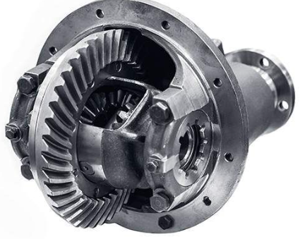
Ring and Pinion Gears
When the driveshaft rotates, the pinion gear rotates the ring gear.
The outer end of the pinion gear is splined to the pinion flange, and the inner end meshes with the teeth of the ring gear.
The pinion gear is typically supported by two opposing tapered roller bearings, allowing it to rotate freely in the axle housing.
Crush sleeves or shims are used to preload the pinion bearings, eliminating end play and excess clearance.
Some differentials use a pinion pilot bearing (commonly a straight roller bearing) to support the inner end during heavy load conditions, indicating a straddle-mounted pinion; overhung pinions use only two tapered roller bearings.
The pinion gear drives the ring gear, transferring power through a 90° angle.
The ring gear is bolted securely to the differential case with multiple evenly spaced bolts.
Ring and pinion gears are manufactured as a matched set; the ring gear is larger with more teeth, producing a gear reduction.
Gears are lapped at the manufacturer to ensure correct meshing, quieter operation, and longer gear life.
When replaced, the ring and pinion are replaced as a matched set.
Key Points:
The ring gear transfers rotation through a 90° angle.
Lapping is performed at the manufacturer using an abrasive compound to ensure the gears mesh correctly with no high or low spots.
Always replace the ring and pinion as a matched set.
Ring and Pinion Gear Types
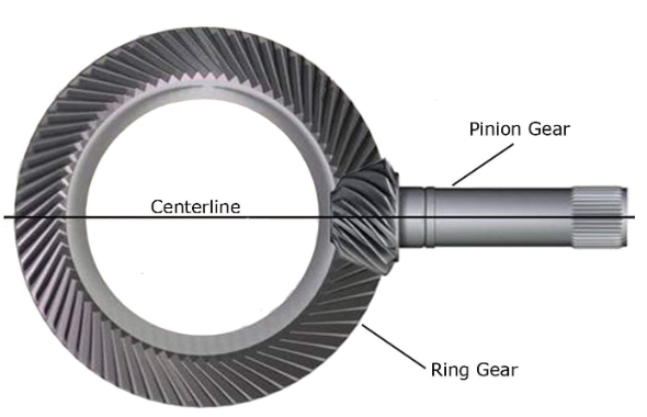
Spiral Bevel Gears
Gear teeth are curved or conical, increasing tooth contact area for quieter operation.
The ring gear and pinion gear share the same centerline.
Some in-line front-wheel-drive (FWD) transaxles use spiral bevel gears.
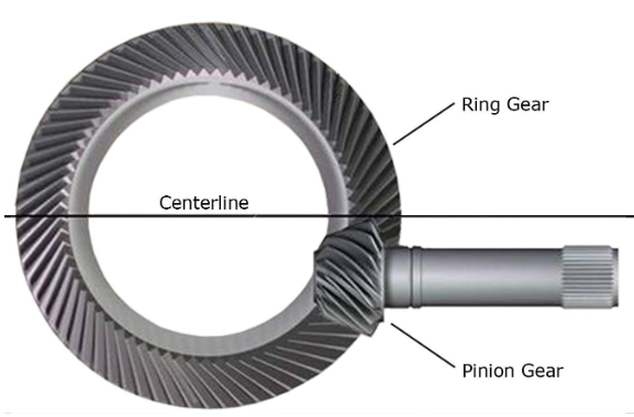
Hypoid Gears
The pinion centerline is lower than the ring gear centerline.
A lower pinion allows a lower driveshaft tunnel, providing more interior space.
Hypoid gears have a larger tooth contact area, producing a quieter gearset with longer gear life.
They are the most common gear type in modern rear-wheel-drive (RWD) vehicles.
Amboid Gears
Often used in trucks, some 4WD front axles, and heavy-duty equipment.
Distinguished by tooth shape and centerline position compared to other gear types.
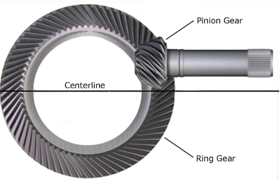
Key point:
The positioning of the amboid gear reduces driveline angularity, which minimizes driveline vibration.
Gear Designs
Hunting Gearset
Gear teeth do not mesh one-for-one during a single revolution of the ring gear.
Provides even wear across all teeth over time.
Non-Hunting Gearset
The same gear teeth mesh during one revolution of the ring gear.
Can cause uneven wear on specific teeth.
Partial Hunting Gearset
Example: 3.50:1 ratio
The ratio ends in a half number (.5).
Combines features of hunting and non-hunting designs.
1. Hunting Gearset
Definition: The gear teeth do not mesh one-for-one during a single revolution of the ring gear.
Operation: Each tooth on the pinion meshes with a different tooth on the ring gear with every revolution.
Advantages:
Even wear across all gear teeth.
Reduces the risk of localized tooth fatigue.
Typically quieter and smoother in operation.
Applications: Common in modern vehicles to increase gear longevity and reduce noise.
2. Non-Hunting Gearset
Definition: The same gear teeth mesh every revolution of the ring gear.
Operation: One pinion tooth always engages the same ring gear tooth.
Advantages:
Simpler design and easier to manufacture.
Can be slightly more efficient in power transfer.
Disadvantages:
Uneven wear on the teeth that mesh repeatedly.
Can lead to earlier gear fatigue and potentially more noise over time.
Applications: Older vehicles or applications where manufacturing simplicity is prioritized.
3. Partial Hunting Gearset
Definition: A hybrid design where some teeth mesh repeatedly, but the pattern shifts partially with each revolution.
Operation: A ratio like 3.50:1 is typical; the ratio always ends in .5, indicating the teeth pattern shifts slightly every revolution.
Advantages:
Offers better wear distribution than a pure non-hunting set.
Retains some predictable tooth engagement.
Disadvantages:
More complex to design than non-hunting sets.
Slightly less uniform wear than full hunting gearsets.
Applications: Some rear axle assemblies and specialty differentials where a balance between gear wear and manufacturing constraints is needed.
Part 2
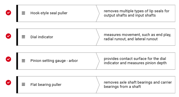
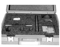
Gauging Tools
Servicing the Rear Axle – Special Tools Overview
Servicing the rear axle requires several specific tools, including:
Torque multiplier
Pinion setting gauge kit
Bearing pullers
These tools help diagnose concerns and perform service procedures accurately.
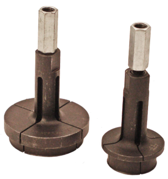
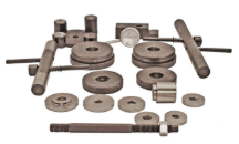
Pinion Setting Gauge Kit
Used to measure pinion shim thickness before installing the pinion.
Kits typically include multiple components to fit various axle assemblies.
Always identify the axle size before selecting components.
Incorrect component selection will result in incorrect shim measurements.
Caution: These are precision-machined tools—if dropped or damaged, readings will be inaccurate.
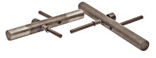
Main Components of the Pinion Setting Gauge Kit
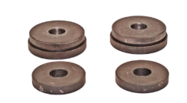
Side Bearing Discs
Installed in place of carrier bearings.
Held in place by carrier bearing retainers.
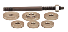
Gauge Discs
Installed inside the differential housing near the rear (inner) pinion bearing.
Measurement of shim thickness is taken at this location.
Front and Rear Pilot Washers and Bolt
Used to retain the gauge discs in position.
Arbor
Attaches to the side bearing discs.
Acts as the fixture where the dial indicator mounts.
Must move freely in the side bearing discs.
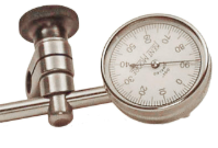
Dial Indicator
Mounted to the arbor.
Measures pinion shim thickness directly.
Using the Pinion Setting Gauge
The gauge determines the base shim thickness needed for proper pinion placement.
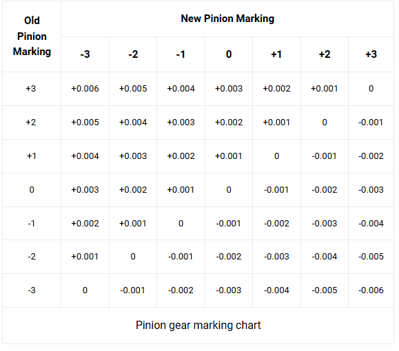
Some pinions have a numeric mark (+ or -) indicating an adjustment from the base shim.
Positive (+) mark: Subtract from base measurement.
Example: Base 0.037 in., mark +3 (0.003 in.) → Final shim = 0.034 in.
Negative (–) mark: Add to base measurement.
Example: Base 0.037 in., mark –2 (0.002 in.) → Final shim = 0.039 in.
Always follow manufacturer service information, as procedures vary by vehicle.
Pinion Gear Marking Chart
Some service manuals include a pinion gear marking chart.
The chart helps determine necessary changes in shim depth for correct gear alignment.
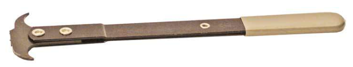
Bearing Puller Attachment
Bearing Puller Attachment Overview
Purpose:
Used to remove bearings, races, or gears from shafts or housings without causing damage.
Commonly used in rear axle service to remove differential, pinion, or carrier bearings.
Function:
The puller grips the inner or outer race of the bearing.
A forcing screw or slide hammer applies even pulling force to extract the bearing straight off its seat.
⚙ Main Components of a Bearing Puller Attachment
Jaws or Clamps:
Grip the bearing (inner or outer race).
May be adjustable or reversible to fit different bearing sizes.
Crossbar or Yoke:
Connects the jaws and serves as the mounting point for the forcing screw or slide hammer.
Forcing Screw / Center Bolt:
Provides the mechanical pulling force by tightening against the shaft or housing.
Adapters and Spacers:
Allow the tool to fit various axle or bearing types.
🧰 Common Variations
Two-Jaw Puller
Two adjustable arms grip opposite sides of the bearing.
Good for limited access areas.
Must be centered properly to prevent tilting or damage.
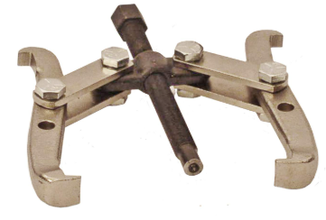
Three-Jaw Puller
Three evenly spaced jaws offer balanced pulling force.
Reduces risk of cocking the bearing during removal.
Commonly used for larger bearings or gears.
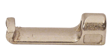
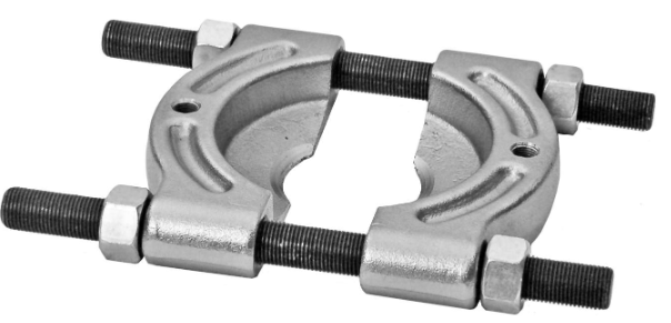
Bearing Splitter (Separator) Attachment
Two thin, wedge-shaped halves slide behind the bearing or race.
Bolts clamp the halves together to grip the bearing.
Often used with a puller bar and forcing screw or a slide hammer.
Ideal for flush-mounted or recessed bearings.
Slide Hammer Attachment
Connects to a puller or bearing adapter.
A sliding weight impacts a stop to deliver impact pulling force.
Useful when a bearing is stuck or press-fitted tightly.
Internal Bearing Puller
Expands inside a bearing or race from the inner diameter.
Used when you can’t access the outer race (e.g., in blind housings).
Typically paired with a slide hammer for removal.
⚠ Safety and Usage Tips
Always inspect bearings before removal—reuse only if approved by service info.
Apply steady, even pressure; avoid using heat unless specified.
Lubricate puller threads for smoother operation and less tool wear.
Protect machined surfaces from scratches or gouges during removal.
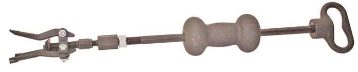
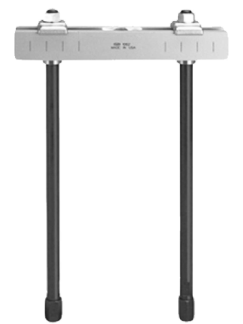
Blind Hole Bearing Puller
Purpose:
Designed to remove bearings located in blind holes (where the bearing cannot be pushed out from behind).
Commonly used in transmissions, differentials, and axle housings.
⚙ Construction and Components
Slide Hammer Attachment:
The puller attaches to the end of a slide hammer.
The hammer provides the impact force needed to extract the bearing.
Threaded Center Post:
Rotating this post causes the puller arms to expand outward.
Expanding Arms:
The arms expand inside the bearing bore.
Each arm has a lip at the bottom that catches under the inner edge of the bearing.
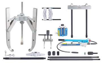
Overview of Pullers in the Automotive Industry
Purpose:
Used to pull one component off another, typically when they are press-fitted together.
Commonly remove bearings, bushings, pulleys, and gears.
Variety:
Available in many sizes and configurations, depending on the component and access area.
All serve the same basic function — to apply controlled pulling force for safe removal.
⚙ Operation and Force Types
Manual Pullers:
Operated by turning a pressure screw with hand tools.
Provide precise control for smaller components.
Hydraulic Pullers:
Use fluid pressure to apply greater pulling force.
Common for large, tightly fitted components.
Combination Tools:
Pullers may be used with slide hammers or adapters to improve pulling efficiency.
Especially useful for press-fit or recessed parts.
🧰 Common Puller Components
Puller Jaws:
Grip the part being removed (e.g., bearing, gear).
Can be two-jaw or three-jaw types for different access angles and force balance.
Pressure Screw:
The central threaded bolt that provides mechanical pulling force.
As the screw is tightened, it draws the jaws or adapter against the part.
Puller Body (Yoke):
The main frame holding the tool together.
Supports the pressure screw and connects to the jaws or adapters.
🔩 Types of Puller Bodies
Bar Yoke Puller
Straight bar design with pressure screw in the center.
Has slots at both ends for adjustable jaw or bolt placement.
Used with puller jaws or bolts depending on the application.
Common for general-purpose pulling tasks.
Bridge Yoke Puller
U-shaped design with a center-mounted pressure screw.
Often used with bearing cup pullers.
The pressure screw pulls the component directly out of its bore.
Provides a stable structure for even force distribution.
⚠ Key Notes
Pullers are typically made from high-strength steel to handle significant tension loads.
Always center the pressure screw to avoid damaging components.
Lubricate threads before use for smoother operation and less wear.
Use appropriate size and type of puller for the specific component to prevent slippage or breakage.