WELLBORE STABILITY APPLICATION
Components of Wellbore Instability
Fluid Shale Interaction
Unbalanced Stress
FLUID-SHALE INTERACTION
Shale: a fine-grained, sedimentary rock primarily composed of clay minerals and silt-sized particles.
low permeability
low tensile and compressive strength
Due to hydration and swelling
Clay Minerals: Shales often contain clay minerals (smectite) that swell when exposed to water-based drilling fluids. This leads to reduced mechanical strength and increased instability
Cation Exchange: Water entering the shale matrix may displace stabilizing cations, causing further weakening
Diagenesis
Over time, burial of sediments causes compaction, reducing porosity and permeability. As smectite transforms into illite, it releases water.
Drilling a hole and giving the sediments access to water can reverse the process (rocks turned into sediments).
Hydratable (Swelling) and Dispersable Shales
Feature | Swelling Shale | Dispersive Shale |
Definition | Expands due to water absorption by clay minerals | Breaks apart or disperses into fine particles when exposed to water |
Clay Type | Smectite | Kaolinite, Illite, Chlorite |
Mechanism | Water enters the clay structure, causing hydration swelling | Water weakens the cohesive forces between the clay particles, leading to dispersion |
Effect on wellbore stability | Borehole narrowing due to volumetric expansion of clays | Borehole enlargement or washout due to the dispersion of particles into the drilling fluid |
Implications of Poor Shale Inhibitions (Ability to slow down the hydration, swelling and disintegration of clays and shales)
Wellbore Instability: Hydration swelling, Disintegration, Collapse
Operation Challenge: Stuck pipe, Loss circulation
Mechanism of Various Types of Shale Inhibitors
Potassium System
PHPA System
Amine System
Glycol System
Design workflow towards optimum shale inhibition
CEC (higher CEC - swelling, lower CEC - dispersive)
XRD Analysis
Capillary Suction Time
Shale Discovery Test/Dispersion Test
Accretion Test
Line Swelling Test
UNBALANCED STRESS
Earth Stresses (also known as in situ stresses or far-field stresses)
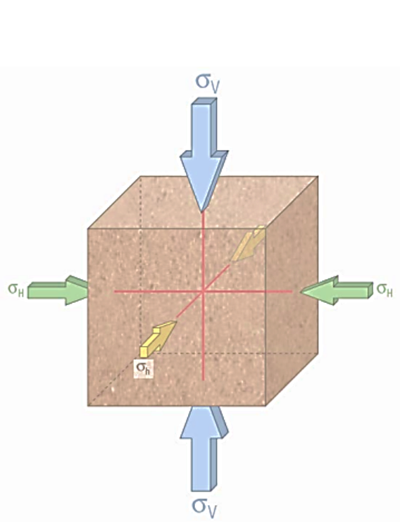
Stress Regimes
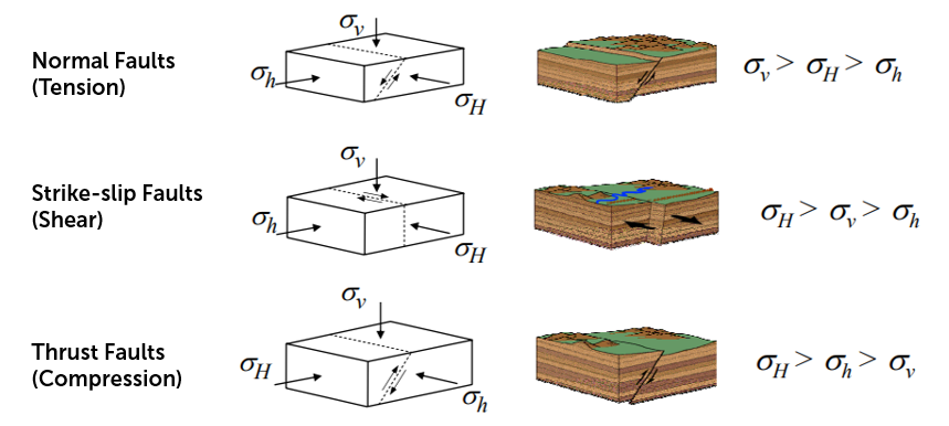
The Basics
In a vertical wellbore, the mud column must provide a stabilizing force to compensate for the loss of the forces from the rock
But the mud doesn’t have to provide the full amount of the missing restraining force since rock has its inherent strength
In a horizontal wellbore, the mud column have to provide the missing restraining force from below
Tunnel Failure (Classic Instability → Requires More Mud Weight)
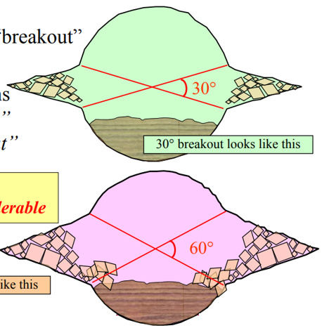
Wellbore fails due to the stress on the wall. If mud weight is not quite adequate, wellbore fails at the side.
Failure is called Breakout and the severity of the failure called Angle of Breakout
Principal Stresses at the Wellbore
Near-wellbore stress state (Axial, Radial, and Tangential Stress)
Tangential/Hoop stress = f(in situ stress, well parameter) - Pw/MW - Pp
If MW increases, Pw increases, Hoop stress decreases
Radial stress = Pw - Pp
If MW increases, Pw increases, Radial stress increases
Mohr Coulomb to obtain shear strength line. Any stress that overpasses the shear strength line will encounter shear failure
Far Field stress state
Wellbore Deformation
Shear failure (90 degree from maximum stress or in direction of minimum stress) favored by:
Low Pw (Wellbore pressure)
Big difference in stress
Low rock strength
Tensile failure (90 degree of minimum stress or in direction of maximum stress) favored by:
High Pw
Managing Tunnel Failure
Depending on the stress regime, the mud weight requirement may depend on well inclination and azimuth (Refer to stereonet and sensitivity plot)
Stereonet refers to collapse pressure where MW must be higher than PP and collapse pressure to avoid hole collapse and maintain in safe mud window.
Normal and Reverse Regime has different mud weight strategy for borehole stability.
Bedding Plane Failure
Occurs when well path’s/trajectory ‘angle of attack’ is near parallel to the bedding plane.
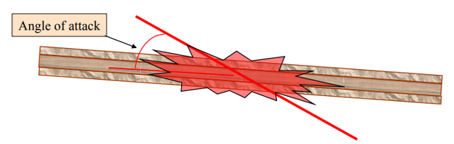
Usually occur at connections
The rocks have no ability to resist being split apart by the mud pressure. The rock is then ‘supercharged’ and will fail when ECD is relieved
Hole Failure Diagnosis (Differences between Classic and Bedding Plane Failure)
Classic Failure | Bedding Plane Failure |
Minimal cavings | Distinct plate look. Small |
No pack-offs when drilling | Cavings easily enter into the hole |
Heavy cavings flow when back-reaming | Pack-off after failure |
Can get rough with the hole | Difficult to be gentle enough |
Long periods wellbore failure | Occurs near-parallel to bedding plane |
Responds to MW increase | Pack-off common in drilling mode |
Cavings random gravel shapes | Worse with increased MW |
Pre-Existing Fractures
Due to natural fracture such as earthquake or faulting
Rock is mechanically weakened and exhibits high fluid flow path with low permeability reservoir matrix
In overbalance drilling - drilling mud enters fractures resulting in loss of circulation and damaging formation. Also, it weakens mechanical strength of formation.
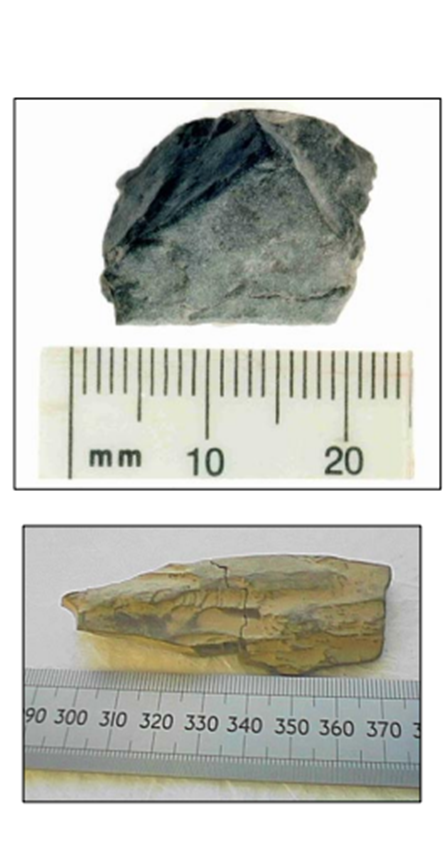
Type of cavings
Splintered Cavings | 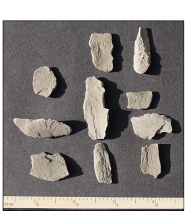 |
|
| |
Angular Cavings |
|
|
| |
Platy/Tubular Cavings | 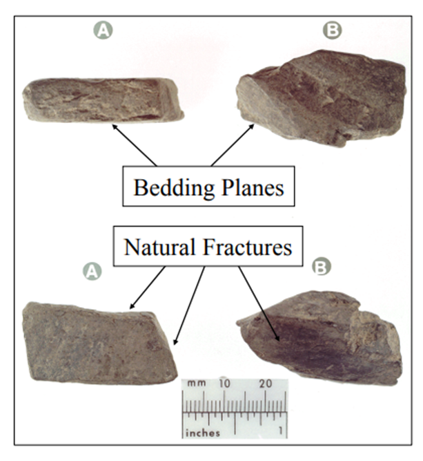 |
|
|
Time-Dependent Shale Instability
When fluid invades, the pore pressure in shale increased. But the P cant be dissipated due to low permeability characteristics of shale.
Hence the pore pressure near to the wellbore can be supercharged higher.
With time, shale started to show sign of collapsing
remedial:
MW is increased until the differential P (used to balance and stabilize the shape of wellbore) is increased to the supposed differential P
BUT, MW cant be further increased to avoid surpassing Fracture Gradient!