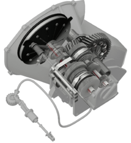
Transverse-mounted Manual Transaxle
Manual Transaxle Operation
The manual transaxle:
The purpose of the manual transaxle is to multiply and transmit engine power to the drive wheels of a vehicle.
It uses a clutch to disengage the engine from the transaxle, allowing the driver to shift into another gear.
The transaxle contains input and output shafts that rotate separately from each other.
A countershaft is also used to transfer power between the input and output shafts.
Each shaft has helical speed gears that mesh with the countershaft gears for all forward speeds.
The reverse gear typically uses a straight-cut spur gear.
These shafts and gears work together to let the driver upshift and downshift the transaxle as needed.
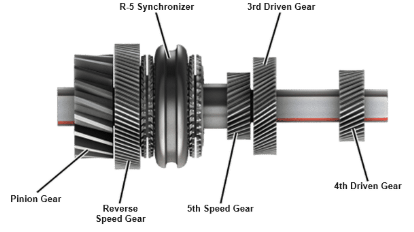
Output Shaft
The output shaft typically has the pinion gear machined onto its end.
It drives the final drive ring gear and differential.
The shaft has gears either pressed on or machined into it to transfer rotational power from the speed gears to the input shaft and then to the pinion gear.
Two bearings support the output shaft—one at each end.
The output shaft shown includes the reverse and fifth speed gears, along with the reverse and fifth synchronizer.
It also has two fixed gears called the third and fourth driven gears.
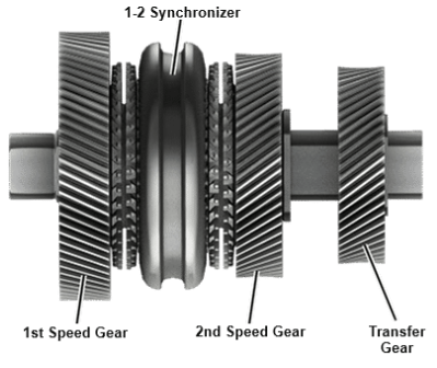
Intermediate Shaft
Some transaxles use a third shaft, called the intermediate shaft, to shorten the transaxle and save space for tight operating areas.
The transaxle shown includes the first and second speed gears on this shaft, with the 1–2 synchronizer positioned between them.
The intermediate shaft also has a fixed gear known as the transfer gear.
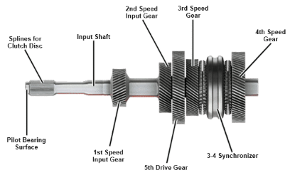
Input Shaft
The input shaft is splined to the clutch disc and drives all other internal components of the transaxle.
It is typically located above the output shaft.
Depending on the transaxle design, the tip of the input shaft may use a pilot bearing to support the front of the shaft.
A front main bearing supports the load placed on the input shaft from the engine and clutch.
The input shaft shown includes the third and fourth speed gears, along with the 3–4 synchronizer.
It also has three fixed gears: the first and second input gears, and the fifth drive gear.
Engage the Clutch
The driver releases the clutch pedal
The release bearing slides back and releases the pressure plate diaphragm spring
The engine power is transferred when the clutch makes contact with the pressure plate
Disengage the Clutch
The clutch pedal is depressed
The clutch release bearing presses on the diaphragm spring fingers
The fingers act as a lever and pull the pressure plate
The engine power is disconnected