AirMatConRep-FINALS Reviewer
ADVANCED AIRCRAFT MATERIALS
Lesson 8: Rubber and Synthetic Rubber
- How are aircraft tires built? - Aircraft Nerds
RUBBER AND SYNTHETIC RUBBER
Aircraft Tires Construction
Aircraft tires are vital components designed to withstand extreme conditions during takeoff, landing, and taxiing.
These tires are meticulously constructed using a combination of natural and synthetic rubber compounds, each offering specific properties essential for aviation safety and performance.
Introduction to Synthetic Rubber
During periods of natural rubber scarcity, such as during war years, the aviation industry turned to synthetic rubber for tire manufacturing.
Five primary types of synthetic rubber have been developed commercially and are extensively utilized across various industries, including aviation.
Natural Rubber
Natural rubber, derived from the sap of certain plants, is a polymer of isoprene.
It possesses excellent flexibility, tensile strength, and resilience, making it ideal for tire and tube applications.
Natural rubber can be vulcanized to achieve varying degrees of hardness, but it deteriorates more rapidly when exposed to air, ozone, light, heat, and certain chemicals.
Synthetic Rubber
Synthetic rubbers, like their natural counterpart, are polymers or copolymers with properties resembling plastics.
Commercially available in various forms such as latex, sheets, tubes, extrusions, moldings, fabrics, sponge materials, cements, and adhesives.
Synthetic rubbers offer advantages such as enhanced durability, resistance to environmental factors, and versatility in manufacturing processes.
2.1 Buna S (GR-S): Government Rubber Styrene
Chemical Composition:
- Buna S is a copolymer synthesized from two primary monomers: butadiene and styrene.
- The name "Buna S" is derived from the first syllable of butadiene ("Bu"), the chemical symbol for sodium ("Na"), used historically as a catalyst in butadiene polymerization, and "S" representing styrene.
Properties and Applications:
- Buna S exhibits the capability to be vulcanized with sulfur and cured to attain a hardness comparable to hard rubber.
- To optimize its physical properties, Buna S must be compounded with additives such as carbon black, typically resulting in a black-colored material.
- Widely employed as a substitute for natural rubber, Buna S finds extensive usage in various applications, particularly in tire and tube manufacturing.
- Its versatility allows it to replace natural rubber across a wide range of applications due to its durability and resilience.
2.2 Buna N (GR-A): Government Rubber-Acrylonitrile
Chemical Composition:
- Buna N is a copolymer synthesized from butadiene and acrylonitrile.
- The "N" in Buna N stands for nitrile, reflecting its chemical composition and categorization as a nitrile rubber.
Properties and Applications:
- Buna N shares similarities with natural rubber as it can be vulcanized with sulfur and cured to achieve hardness akin to hard rubber.
- Exhibits exceptional resistance to oil, making it a preferred choice for applications requiring contact with petroleum products.
- Withstands temperatures up to 250°F in normal conditions, but stiffens at -45°F.
- Possesses good abrasion resistance and "breakaway" properties when in contact with metal surfaces, preventing adherence to cylinder walls.
- Adversely affected by ozone and sunlight, necessitating protective measures during storage and usage.
- Properties are enhanced with the addition of carbon black, improving its durability and resilience.
- Utilized extensively in various industries for oil and gasoline hoses, tank linings, hydraulic accumulator bags, gaskets, and seals.
2.3 Neoprene: Government Rubber-Monovinyl Acetylene type
Chemical Composition:
- Neoprene is a polymer derived from chloroprene.
Historical Significance:
- Neoprene holds the distinction of being the first commercially successful synthetic rubber, revolutionizing various industries, including aviation.
Properties and Applications:
- Exhibits excellent resistance to oil and remarkable resistance to heat, air, light, and flame, making it a versatile material for diverse applications.
- Notably superior light resistance compared to other rubber types.
- While capable of vulcanization without sulfur, it cannot achieve the same hardness as hard rubber upon curing.
- Utilized extensively across industries for its durability and resilience, Neoprene finds applications in oil-resistant hoses, carburetor diaphragms, gaskets, shoe soles, barrage balloons, truck tires, cements, tape, and caulking.
2.4 Butyl: Government Rubber-Isobutylene
Chemical Composition:
- Butyl is a copolymer primarily composed of isobutylene, with minor amounts of unsaturated hydrocarbons like butadiene or isoprene.
- Derived from petroleum by-products, particularly isobutylene, making it a cost-effective synthetic rubber option.
- Additionally known as "Flexon."
Properties and Applications:
- Despite being vulcanizable with sulfur, Butyl cannot achieve the same hardness as hard rubber upon curing.
- Exhibits exceptional gas impermeability, making it an ideal choice for applications requiring containment or resistance to gas permeation.
- Widely utilized in tire tubes due to its superior gas impermeability, ensuring optimal tire pressure retention.
- Finds applications in diverse industries, including gas masks, plywood molding bags, life jackets, and chemical storage, where impermeability and resilience are critical requirements.
2.5 Thiokol: Government Rubber-Polysulfide
Chemical Composition:
- Thiokol is a polysulfide polymer, renowned for its exceptional chemical structure and properties.
- Sometimes referred to as polysulfide synthetic rubber.
Properties:
- Exhibits the highest resistance to deterioration among synthetic rubbers, making it particularly suitable for harsh environments.
- While possessing lower physical properties compared to other synthetic rubbers, Thiokol excels in resistance to aromatic hydrocarbons and aromatic blended gasolines.
- Capable of vulcanization with zinc oxide, albeit unable to achieve the hardness comparable to hard rubber.
Applications:
- Widely utilized in various industrial applications due to its superior resistance to chemicals and environmental factors.
- Commonly employed in oil hoses, tank linings for aromatic aviation gasolines, paint spray hoses, gaskets, and seals, where durability and chemical resistance are paramount.
AIRCRAFT PLASTICS
INTRODUCTION
Plastics encompass a diverse range of synthetic and natural organic materials capable of being molded, cast, extruded, or fabricated into various shapes under heat and pressure. Their utilization in aircraft applications has expanded significantly, mirroring advancements in the field.
HISTORY
- The earliest plastic, celluloid, originated from treating cotton cellulose with nitric acid.
- Casein plastic, derived from sour milk mixed with formaldehyde, found commercial use in buttons and buckles.
- Bakelite, a breakthrough, resulted from mixing phenol and formaldehyde, marking the onset of significant plastic development. Similar materials include Micarta and Formica, collectively known as phenolics.
- Plastics are created through polymerization, a chemical process yielding compounds with increased molecular weight compared to the original substance.
Plastics play an integral role in aviation, serving diverse functions such as manufacturing aircraft components, fairings, emergency hatch covers, and control-surface tabs. Understanding their history and properties is essential for leveraging their capabilities effectively in aircraft design and production.
CLASSIFICATION OF PLASTICS
Plastics are divided into two main categories based on their response to heat: thermoplastics and thermosetting plastics.
1. Thermoplastics:
- Soften when heated and harden when cooled.
- Can be reheated, reshaped, and cooled repeatedly.
- Examples include polyethylene, polypropylene, and PVC.
2. Thermosetting Plastics:
- Undergo chemical change upon initial heating, becoming infusible thereafter.
- Do not soften upon further heating and cannot be reshaped once fully cured.
- Thermosetting-plastic laminates, although partially cured, can be reshaped after a final heating, a process known as postforming.
- Examples of thermosetting plastics include phenolics, epoxies, and polyesters.
THERMOPLASTIC
1. CELLULOSE ACETATE:
- Historically used in early aircraft due to its transparency and lightweight nature.
- Prone to shrinkage and yellowing over time, leading to its replacement in modern aircraft.
- Can be identified by its slight yellow tint and the production of a sputtering flame and dark smoke when burned.
- Identified through an acetone test, softening upon application of acetone.
2. ACRYLIC PLASTICS:
- Identified by trade names such as Lucite or Plexiglas.
- Stiffer and more transparent than cellulose acetate, with virtually colorless properties.
- Burns with a clear flame and emits a relatively pleasant odor.
- Acetone application leaves a white residue but does not soften the material, distinguishing it from cellulose acetate.
- Acrylic windshields are often referred to as "lifetime windshields" due to their longevity compared to cellulose acetate.
THERMOSETTING CURING STAGES OF RESINS
Thermosetting resins progress through three curing stages: A, B, and C.
- A Stage:
- Resin components are mixed but haven't begun chemical reaction.
- Common during wet layup procedures.
- B Stage:
- Chemical reaction has started, causing resin to thicken and become tacky.
- Prepreg materials use resins in this stage.
- Curing can be paused by freezing; resumes upon warming.
- C Stage:
- Resin is fully cured, either at room temperature or through elevated temperature cycles.
AIRCRAFT COMPOSITES
INTRODUCTION
Composite materials play a crucial role in aerospace construction due to their advantages over traditional materials like aluminum. They offer high strength, low weight, and corrosion resistance, making them ideal for aircraft parts such as fairings, spoilers, and flight controls. Modern aircraft even feature all-composite fuselage and wing structures, demanding specialized knowledge for their repair.
LAMINATED STRUCTURES
Composites are formed by combining materials with distinct properties while retaining their individual identities. Typically, they consist of fibrous materials embedded in a resin matrix, laminated with fibers oriented for strength and stiffness. Applications of composites in aircraft range from fairings to primary wing and fuselage structures, highlighting their versatility and utility.
MAJOR COMPONENTS OF A LAMINATE
1. Fiber:
- Primary load-bearing element of the composite, providing strength and stiffness.
- Mechanical properties are optimized by orienting fibers, though composites can't match metals' isotropic nature.
2. Matrix:
- Supports and bonds fibers together.
- Transfers applied loads to fibers, maintains their orientation, and provides environmental resistance.
- Determines the composite's maximum service temperature.
Understanding the composition and properties of composite materials is essential for designing and maintaining aircraft structures, ensuring optimal performance and safety in aerospace applications.
TYPES OF FIBERS
1. Reinforcing Fibers:
- Provide primary structural strength to composites when combined with a matrix.
- Can be used alone or in conjunction with other fibers (hybrids).
- Woven into specific patterns for optimized performance (fiber science).
- Combined with other materials like rigid foams for sandwich structures.
- Used in combination with various matrix materials for diverse applications.
2. Fiberglass (Glass Cloth):
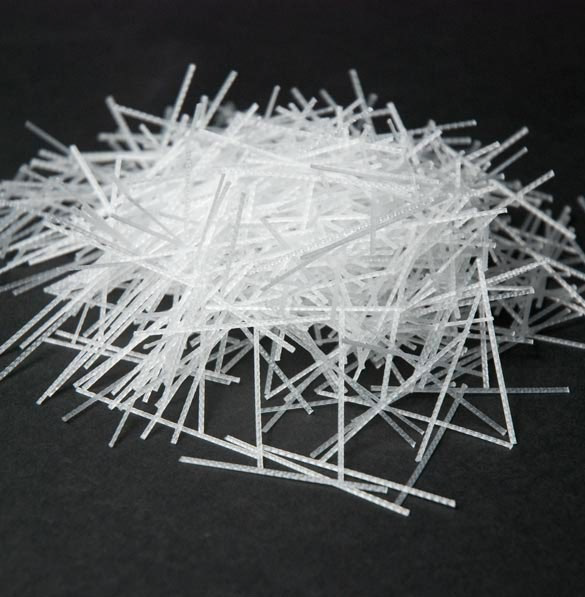
- Fiberglass, made from small strands of molten silica glass spun together and woven into cloth, is commonly utilized in aircraft non-structural composites.
- It is available in two main types:
- E-glass (borosilicate glass): Known for its high resistivity to current flow, hence sometimes referred to as "electric glass." E-glass is the most commonly used type for reinforcement.
- S-glass (magnesia-alumina-silicate): Used when very high tensile strength is needed.
- Despite its widespread use due to affordability and availability, fiberglass is typically heavier and less strong compared to other composite fibers.
- Fiberglass can be applied in various composite structures, although its weight and strength limitations should be taken into consideration for optimal performance.
3. Aramid:
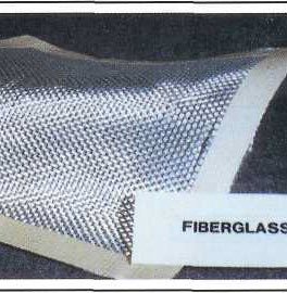
- Aramid, commercially known as Kevlar, possesses remarkable properties:
- High tensile strength, exceptional flexibility, and stiffness.
- Low compressive properties and excellent toughness.
- Kevlar composite material exhibits approximately four times the tensile strength of alloyed aluminum.
- Aramid fibers are non-conductive and do not induce galvanic reactions with metals.
- Ideal for aircraft parts subject to high stress and vibration.
- Aramid fiber bundles are sized by weight rather than the number of fibers.
- Characterized by its yellow color, available in various grades and weaves for different applications.
- Kevlar 49 is primarily used in aircraft composite reinforced plastics, in both thermoplastic and thermosetting resin systems.
4. Carbon/Graphite:
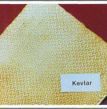
- Carbon fibers are produced in an inert atmosphere through the pyrolysis of organic fibers like rayon, poly-acrylonitrile, and pitch.
- The terms "carbon" and "graphite" are often used interchangeably.
- Advantages include high strength and corrosion resistance.
- Disadvantages include lower conductivity than aluminum, necessitating lightning protection measures for parts prone to strikes, and high cost.
- Carbon fibers can cause galvanic corrosion when used with metallic fasteners and structures due to being cathodic compared to anodic aluminum and steel.
- Carbon/graphite materials should be kept separate from aluminum components with sealants and corrosion barriers like fiberglass.
- Carbon fibers are very stiff and strong, 3 to 10 times more than glass fibers.
- Utilized in structural aircraft applications such as floor beams, stabilizers, flight controls, primary fuselage, and wing structure.
5. Boron:
- Boron fibers are manufactured by depositing boron onto a thin tungsten filament, resulting in fibers approximately 0.004 inches in diameter.
- Possesses excellent compressive strength, stiffness, and hardness.
- Despite its advantageous properties, boron is not widely used in civil aviation due to hazards and high costs.
- In civil aviation, hybrid composite materials of aramid and carbon/graphite are preferred over boron.
- Boron fibers are primarily utilized in military aviation applications.
- Used for repairing cracked aluminum aircraft skins due to its thermal expansion closely matching aluminum and absence of galvanic corrosion potential.
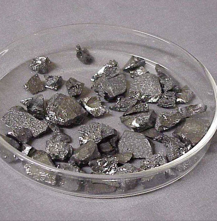
6. Ceramic:
- Ceramic fibers are employed in high-temperature applications, such as turbine blades in gas turbine engines.
- Retains significant strength and flexibility up to temperatures of 2,200°F.
- Commonly used in civilian aviation in conjunction with a metal matrix for high-temperature requirements.
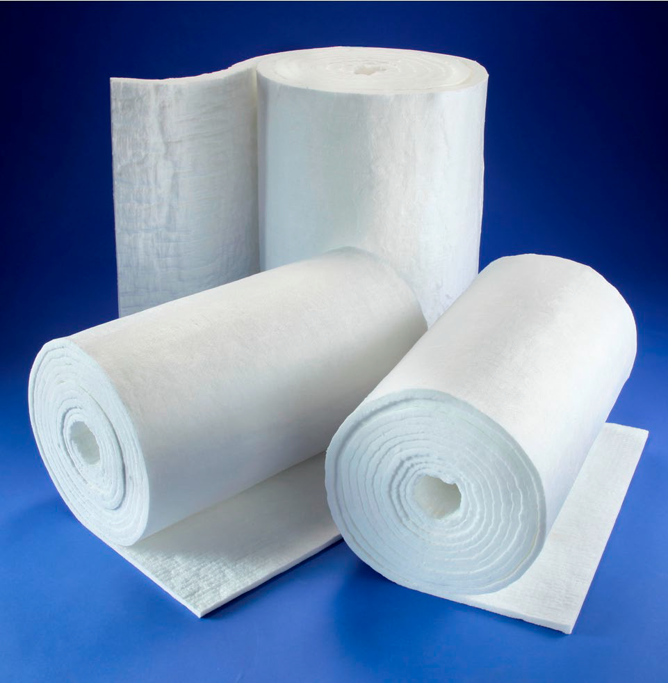
- Special ceramic composites are utilized in tiles on the Space Shuttle for rapid heat dissipation.
- Ceramic-fiber composites are also utilized in some firewalls for their thermal properties.
TYPES OF FIBER-REINFORCED COMPOSITES
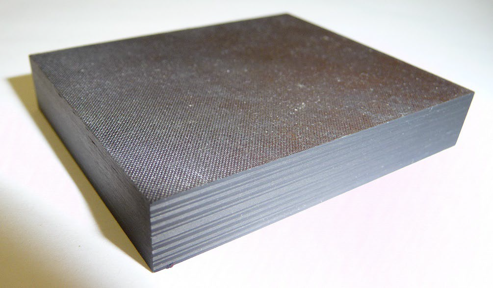
1. LAMINATED COMPOSITES
- Consist of two or more layers of reinforcing material bonded together with a resin matrix.
- Built up to desired thicknesses using multiple layers of reinforcing fabrics.
2. SANDWICH COMPOSITES
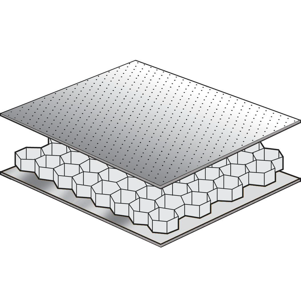
- Feature two or more laminated face sheets bonded to each side of a lightweight core.
- Offer high strength-to-weight ratios compared to solid laminated structures.
CORE MATERIALS
- Central members of an assembly used extensively in advanced composite construction.
- Sandwich construction involves bonding a core material between thin face sheets, providing rigidity and lightweight characteristics.
- Core materials contribute significant compressive strength to structures.
HONEYCOMB CORES
- Consist of a six-sided shape resembling natural honeycomb, offering a high strength-to-weight ratio.
- Ribbon direction denotes the direction in which the honeycomb can be pulled apart.
- Honeycomb comes in various core configurations, each with unique properties.
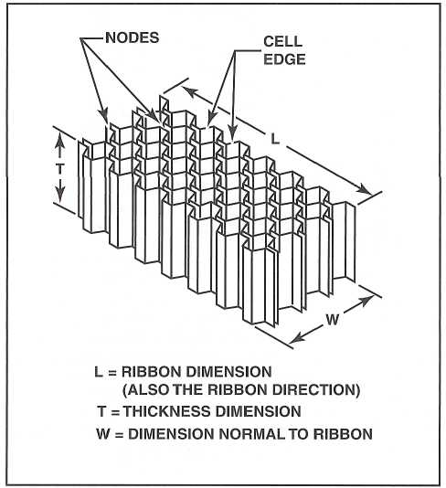
TYPES OF HONEYCOMB CORES
1. Kraft Paper:
- Relatively low strength but good insulating properties.
- Available in large quantities and at a low cost.
2. Thermoplastics:
- Offer good energy absorption and/or redirection.
- Provide smooth cell walls, moisture and chemical resistance.
- Environmentally compatible, aesthetically pleasing, and relatively low cost.
3. Aluminum:
- Best strength-to-weight ratio among honeycomb cores.
- Good heat transfer properties and electromagnetic shielding.
- Smooth, thin cell walls, machinability, and relatively low cost.
4. Steel:
- Offers good heat transfer and electromagnetic shielding properties.
- Heat-resistant and suitable for high-temperature applications.
5. Aramid Paper:
- Flame-resistant and fire-retardant.
- Exhibits good insulating properties and low dielectric properties.
- Allows for good formability in composite structures.
6. Fiberglass:
- Tailorable shear properties by layup.
- Low dielectric properties and good insulating properties.
- Offers flexibility and formability in composite applications.
7. Carbon:
- Provides high dimensional stability and retention.
- Exhibits high-temperature property retention and stiffness.
- Very low coefficient of thermal expansion but comes at a high cost.
8. Ceramics:
- Heat resistant to very high temperatures.
- Offers good insulating properties and is available in small cell sizes.
- However, ceramics are among the most expensive honeycomb core materials.
FOAM CORES
- Offer different densities and temperature characteristics for various applications.
- Styrofoam and urethane foam are commonly used, each requiring specific resin types.
- Used in homebuilt and lighter aircraft for strength and shape in various components.
WOOD CORES
- Balsa wood or laminations of hardwood bonded to high-strength laminates.
- Provide high compressive strength to composite structures in sandwich construction.
Lesson 9: DESTRUCTIVE AND NON-DESTRUCTIVE TESTING
Non-Destructive Testing (NDT) Overview:
- NDT is crucial in aerospace for detecting flaws without causing damage.
- It's used in design, manufacture, and maintenance to evaluate material properties.
Destructive Testing:
- Tests materials to failure to evaluate robustness and identify failure points.
- Used for determining physical properties of materials and components.
Non-Destructive Testing Methods:
1. Visual Inspection:
- Fundamental method using light, mirrors, and magnification.
- Borescope is used for detailed inspections.
2. Liquid Penetrant Inspection (LPI):
- Detects cracks and faults on open surfaces.
- Relies on capillary action with specific dwell times.
3. Magnetic Particle Inspection (MPI):
- Detects surface and near-surface discontinuities in iron alloys.
- Part must be magnetized; disruption in magnetic field indicates defects.
- Uses residual magnetism and continuous magnetization methods.
MAGNETIC ORIENTATION
- To detect a crack with magnetic particle inspection, the part must be magnetized so that the lines of flux are perpendicular to the fault.
- Flaws parallel to the magnetic field lines cause minimal disruption, while those perpendicular create noticeable disruptions.
- Residual Magnetization: Magnetizing force is removed before applying the testing medium, relying on the part's residual or permanent magnetism. Used with steels heat-treated for stressed applications.
- Continuous Magnetization: Magnetizing force is applied simultaneously with the testing medium to detect invisible defects with greater sensitivity than residual magnetization.
4. Eddy Current Inspection:
- Detects surface and subsurface flaws in metals.
- Relies on eddy currents induced by electromagnetic fields.
5. Ultrasonic Inspection:
- Uses sound waves to inspect plastics, ceramics, and metals.
- Different systems include pulse echo and resonance.
6. Radiographic Inspection:
- Provides internal photographic views of structures using radiation.
- Factors affecting exposure include material properties, object size, and defect type.
Key Testing Procedures:
- Visual Inspection: Utilizes basic tools like light and magnification.
- Liquid Penetrant Inspection: Relies on capillary action and specific dwell times.
- Magnetic Particle Inspection: Detects disruptions in magnetic fields using residual or continuous magnetization.
- Eddy Current Inspection: Uses induced eddy currents for flaw detection.
- Ultrasonic Inspection: Employs sound waves for material evaluation.
- Radiographic Inspection: Provides internal views using radiation and photographic film.
SET UP AND EXPOSURE for Radiographic Inspection:
- To create a permanent record during radiographic inspection, a sheet of photographic film is placed on one side of the object being inspected, with the radiation source on the other side.
- The film is positioned as close to the specimen as possible, and the radiation source is oriented to penetrate the specimen's density.
- Denser specimens allow less radiation to pass through, resulting in less exposure on the film.
- Factors influencing exposure include material thickness and density, object shape and size, type of defect to be detected, equipment characteristics, exposure distance and angle, film characteristics, and use of intensifying screens.
INSPECTING COMPOSITES:
- Composite structures pose challenges for non-destructive testing (NDT) due to their materials, but several NDT methods are effective for composites.
1. Coin Tap Test:
- Simple yet effective on laminated, bonded, and honeycomb materials.
- Structural flaws are detected by tapping a coin lightly along the suspected damaged area.
- Undamaged areas produce a solid ringing sound, while damaged areas produce a hollow thud.
2. Radiography for Composites:
- X-rays may not be effective on certain bonded structures, but other radiographic methods can detect surface cracks and internal damage in many composite structures.
- Radiography can identify water inside honeycomb core cells.
3. Laser Holography:
- Involves heating a part and photographing it using a laser light source and special camera system.
- Laser holography can detect disbonds, entrapped water, and impact damage in various composite materials.
Lesson 10: CORROSION
Corrosion Overview:
- Corrosion is the chemical or electrochemical deterioration of metal into metallic compounds.
- Corrosive agents initiate corrosion, which can occur internally or on the surface.
Conditions for Electrochemical Corrosion:
- Four conditions necessary for electrochemical corrosion:
1. Presence of a metal susceptible to corrosion (anode).
2. Existence of a dissimilar conductive material with lower corrosion tendencies (cathode).
3. Availability of a continuous, conductive liquid path (electrolyte).
4. Establishment of electrical contact between anode and cathode (e.g., metal-to-metal contact).
Classifications of Corrosion:
1. Direct Chemical Corrosion:
- Results from direct exposure of a surface to caustic liquids or gases.
- Examples include spilled battery acid, flux deposits, or caustic cleaning solutions.
2. Electrochemical Corrosion:
- Involves an electrochemical reaction accompanied by electron transfer between a solid and a liquid.
Types of Corrosion:
A. General Surface Corrosion (Uniform Attack):
- Common form resulting from direct chemical attack on metal surface.
- Initially causes dulling, progressing to a rough and frosted surface.
B. Pitting Corrosion:
- Destructive form characterized by white or gray powdery deposits.
- Leads to tiny pits penetrating deeply into metal; commonly observed in aluminum and magnesium alloys.
C. Concentrated Cell (Crevice) Corrosion:
- Corrosion in metal-to-metal joints or spots covered by foreign material.
- Also known as crevice corrosion, affecting areas with restricted access to oxygen.
D. Active-Passive Cells Corrosion:
- Rapid attack on metals reliant on protective oxide films, often leading to pitting corrosion.
- Involves active-passive cells, with a combination of corrosion mechanisms like pitting and oxygen concentration cell corrosion.
E. Filiform Corrosion:
- Oxygen concentration cell occurring beneath organic coatings.
- Recognized by worm-like corrosion traces beneath paint film, commonly affecting steel and aluminum surfaces.
F. Intergranular Corrosion:
- Attack on grain boundaries of metal alloys, visible in highly magnified cross-sections.
- Grain boundaries react with electrolytes, causing localized corrosion.
G. Exfoliation Corrosion:
- Advanced intergranular corrosion causing surface grains to lift due to expanding corrosion products.
- Commonly observed in extruded metal sections with thin grain boundaries.
H. Galvanic Corrosion:
- Occurs when dissimilar metals contact in the presence of an electrolyte, leading to localized corrosion at the joint interface.
I. Stress Corrosion:
- Corrosion induced by constant or cyclic stress in a corrosive environment.
- Commonly seen in materials under mechanical load, such as aircraft components.
J. Fatigue Corrosion:
- Involves cyclic stress and corrosion, leading to metal failure over time.
- Associated with repetitive loading conditions, affecting components like aircraft structures.
K. Fretting Corrosion:
- Wear corrosion occurring at the interface of two highly-loaded surfaces due to vibration or movement.
- Typically observed in riveted joints on aircraft components, where surfaces experience significant mechanical stress and movement.
CORROSION TREATMENT
Corrosion Treatment:
- All corrosion products should be promptly removed as they continue to cause damage if left on the surface.
- Three basic steps for corrosion treatment:
1. Remove as much corrosion as possible.
2. Neutralize any remaining material.
3. Restore the protective surface film.
Paint Removal and Inspection:
- Corrosion under paint requires complete paint removal for thorough inspection.
- Test unfamiliar paint removers on similar metal before use.
- Avoid using caustic paint removers.
- Mask non-stripped areas with heavy aluminum foil to protect from accidental contact with stripper.
- Water rinseable paint removers with syrupy consistency are suitable for aircraft surfaces.
Treatment of Aluminum Alloy:
- Mechanical corrosion removal:
- Use neutral household abrasive cleaners (without chlorine) for mild corrosion.
- Nylon scrubbers or aluminum wool for more severe corrosion.
- Avoid steel wire brushes or steel wool on aluminum to prevent severe corrosion.
Chemical Neutralization for Aluminum Alloy:
- After corrosion removal, treat with a 5% chromic acid solution to neutralize remaining salts.
- Wash off acid after at least five minutes and allow to dry.
- Alodine treatment (MIL-C-5541) can also neutralize corrosion and form a protective film.
Protective Coating:
- Most aircraft owners use a painted finish for attractiveness and protection against impact damage and corrosion.
- Protective coatings are essential for aluminum alloys, which are alloyed for strength but can corrode without protection.
Cladding with Pure Aluminum:
- Aluminum alloys can be protected and made attractive by coating them with a layer of pure aluminum (cladding).
- Cladding protects against corrosion and enhances appearance.
Surface Oxide Film - Anodizing:
- Anodizing is an electrolytic process used to form a hard, decorative, waterproof, and airtight oxide film on metal surfaces.
- Aluminum oxide film serves as a base for paint adhesion.
- Anodizing is performed by passing a direct current through an electrolytic solution.
Surface Oxide Film - Alodizing:
- Alodizing is a chemical process used for applying a protective film on metal surfaces, particularly for field-fabricated parts or damaged anodized surfaces.
- The process uses chemicals meeting MIL-C-5541 specifications, such as Alodine1201.
- Before alodizing, remove all corrosion and clean the surface thoroughly.
Organic Finish (Paint):
- Paint is widely used for corrosion control on metal surfaces.
- Proper surface preparation is essential for paint adhesion, especially on smooth aluminum surfaces.
- Surface roughening can be achieved with mild chromic acid etch, anodizing, or alodizing.
TREATMENT OF FERROUS METALS
Mechanical Corrosion Removal:
- Effective rust removal methods include abrasive paper, wire brushes, and abrasive blasting.
- Abrasive blasting uses materials like sand, aluminum oxide, or glass beads to thoroughly remove corrosion from unplated steel parts.
Surface Treatment - Chrome Plating:
- Chrome plating creates an airtight coating over ferrous metals, excluding moisture and providing corrosion protection.
- Two types used in aircraft construction are decorative and hard chrome plating.
Surface Treatment - Cadmium Plating:
- Cadmium plating is common for steel aircraft hardware, providing an attractive finish and sacrificial corrosion protection.
- When scratched, the oxides formed on cadmium are dense, airtight, and prevent further corrosion.
Surface Treatment - Galvanizing:
- Steel parts, such as firewalls, are coated with zinc through galvanizing to form a protective oxide film when penetrated by corrosion.
Surface Treatment - Metal Spraying:
- Aircraft engine cylinders can be protected by spraying molten aluminum onto the surface.
- This sacrificial corrosion protection is achieved by melting aluminum wire and blowing it onto the cylinder's surface.
Surface Treatment - Organic Coatings (Paint):
- Paint is commonly used to protect ferrous metals, but proper surface preparation is crucial for good adhesion.
- Dry abrasive blasting is recommended to remove surface oxides and roughen the surface for better paint bonding.
These notes summarize effective methods for treating ferrous metals to prevent corrosion and enhance durability in aircraft construction. Each method serves a specific purpose in protecting against different types of corrosion and environmental factors.
Lesson 11: SAFETY WIRING
Introduction to Safetying:
- Safetying in the aircraft industry refers to securing nuts, bolts, and other components to prevent loosening due to vibration during operation.
- Three primary safetying methods are used: safety-wire, cotter pins, and self-locking nuts, with additional practices like retainer washers and pal nuts for specific applications.
Safetying Methods:
- Wire (Safety-Wire):
- Used on cylinder studs, control cable turnbuckles, and engine accessory attaching bolts.
- Cotter Pins:
- Used on aircraft and engine controls, landing gear, and other actuating points.
- Self-Locking Nuts:
- Used in applications where infrequent removal is required, as repeated removal can reduce locking effectiveness.
- Pal or Speed Nuts:
- Force the nut thread against the bolt thread when tightened and should not be reused after removal.
Safety Wiring Overview:
- Safety wire (or locking-wire) prevents fasteners from loosening due to vibration and indicates proper tightening.
Safety Wiring Methods:
- Single Wrap Method:
- Single piece of wire passes through the turnbuckle's center and wraps around each end.
- Single Wrap Spiral:
- Wire spirals around turnbuckle barrel and passes through the center hole twice.
- Double Wrap Method:
- Two pieces of wire each wrap around one end of the turnbuckle.
- Double Wrap Spiral:
- Similar to double wrap method, but involves spiraling each wire around the turnbuckle barrel.
Safety Wiring Equipment:
Safety Wire:
- Commonly available in diameters ranging from 0.020 to 0.041 inches (0.51 to 1.04mm) made of materials like stainless steel, Monel, Inconel, or copper for specific applications.
- Safety Wire Twisters:
- Used to twist and secure safety wire.
- Safety Wire Tabs:
- Washers used to transfer safety wire force to fastener heads.
- Pre-Drilled Fasteners:
- Fasteners with pre-drilled holes for safety wire applications.
- Drilling Jigs:
- Tools to aid in drilling fasteners for safety wire installation.
Installation of Safety Wire:
- When installing safety wire:
- Pull the wire in the direction of tightening to secure the bolt head.
- Twist the wire evenly to the next bolt.
- Pass the end of the wire through the head of the second bolt and twist it for about three or four turns.
- Cut off excess wire and bend the ends back to prevent injury.
General Wiring Procedures:
1. Use New Wire: Always use new safety wire for each application.
2. Direction of Pull: Insert the wire into the pre-drilled nut/fastener so that all pull tightens the nut/fastener.
3. Loop Orientation: Ensure the loop around the bolt head stays down and does not become slack.
4. Twist Tightness: Twists should be tight and even, with six to eight turns per inch between nuts.
5. Pigtail: Create a 1/4- to 1/2-inch pigtail (three to six twists) at the end of the wire run, bending it back or under to prevent snagging.
6. Tension: Safety wires must be tight after installation but not overly tense to avoid breakage due to normal handling or vibration.