Beat-to-beat Heart Rate Monitor Note
1. What the circuit is trying to do (big picture)
Your heart produces an R‑wave spike every time it beats.
The time gap between two consecutive R‑waves tells you the instantaneous heart‑rate:
The circuit’s job is therefore:
Measure that time gap very accurately.
Take the reciprocal (so “long gap” ➜ “small number”, “short gap” ➜ “large number”).
Output a voltage that is directly proportional to that reciprocal – you can feed it to a meter or micro‑controller.
Everything that follows is just plumbing to achieve those three bullets.
2. The players on the stage
Tag | Part (plain‑English name) | Core job |
|---|---|---|
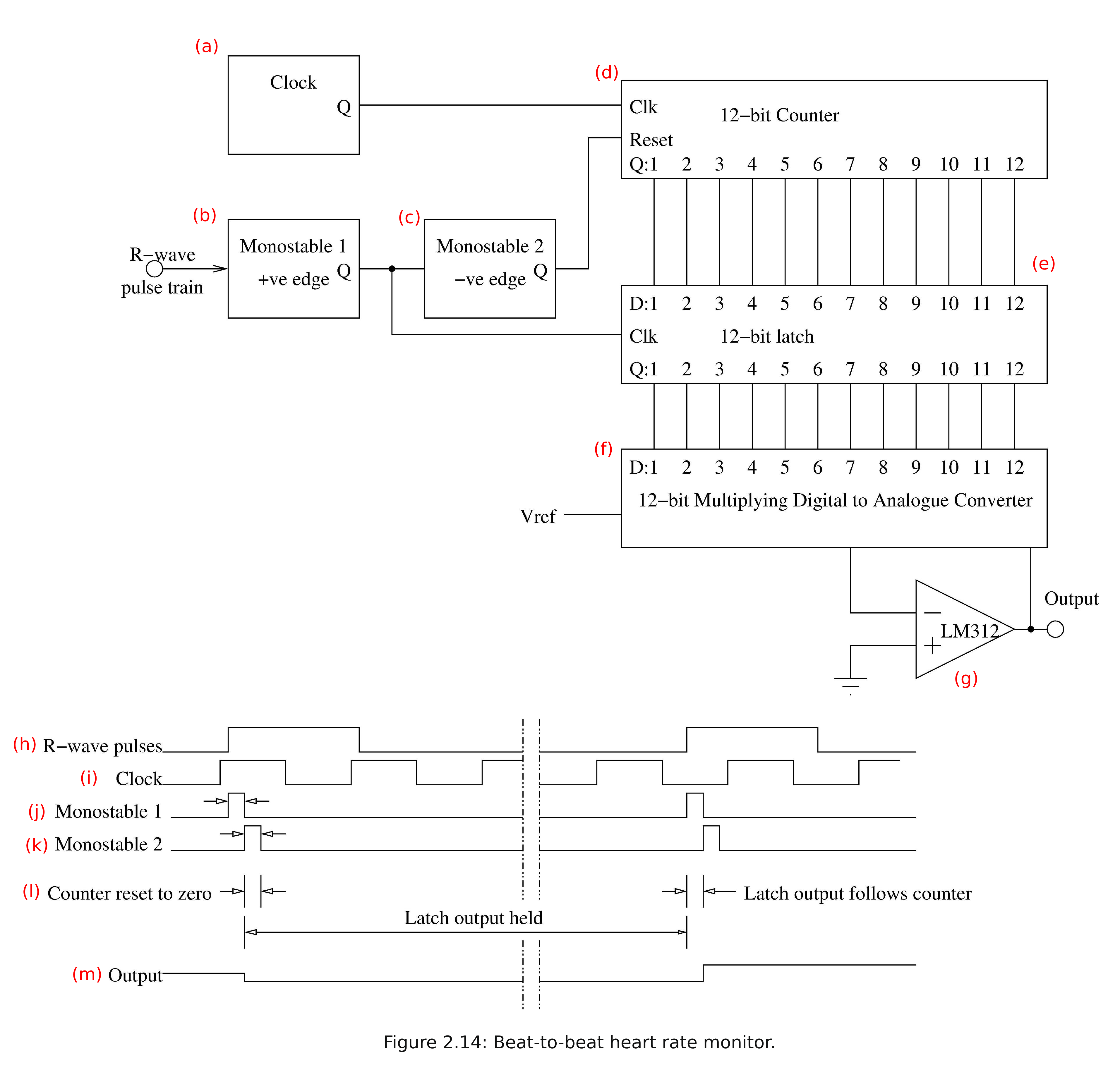
(a) | Clock oscillator | Ticks at a fixed, known rate – the circuit’s “metronome” |
(b) | Monostable 1 (triggered by positive edge of R‑wave) | Generates a short “LOAD‑latch” pulse |
(c) | Monostable 2 (triggered by negative edge produced by Monostable 1) | Generates a short “RESET‑counter” pulse |
(d) | 12‑bit binary Counter | Counts clock ticks while it is NOT reset |
(e) | 12‑bit Latch | Freezes whatever number is present at its input when the LOAD pulse arrives |
(f) | 12‑bit Multiplying D‑to‑A Converter (DAC) | Turns the frozen binary number into a voltage proportional to its reciprocal |
(g) | Op‑amp buffer | Cleans up the DAC voltage so you can drive an external load |
Below the schematic are the matching timing diagrams – each waveform is given a tag (h‑m).
3. One complete heartbeat cycle, step‑by‑step
Think of it like a digital stopwatch that automatically starts, stops, writes its last time to a notepad, clears itself and gets ready for the next lap – all in microseconds.
Stage | What you see in the timing panel | What is physically happening |
|---|---|---|
1. Beat arrives | (h) R‑wave pulse’s rising edge | The spike triggers Monostable 1 (b) |
2. Make a “LOAD” pulse | (j) Monostable 1 goes high for, say, 10 µs | While high, its falling edge will later trigger Monostable 2 |
3. Latch the count Read “Clock, Counter and Latch” section | The high level of (j) is fed as the clock to the Latch (e) | Whatever number is currently on the counter’s outputs is frozen (held) in the latch. Notice how the clock timer takes much longer to iterate the monostable (i vs j). During the time the latch is opened, then closed, and the clock value is reset, there is no change in the clock value anyway, so the timer is not disturbed. |
4. Generate a “RESET” pulse | When (j) falls, Monostable 2 (c) produces a short pulse (k) | This pulse is wired to the Reset input of the Counter (d). The counter returns to zero very briefly. |
5. Stopwatch restarts automatically | (l) shows the brief reset interval; as soon as (k) ends, the counter resumes counting the constant clock (i) | From this moment until the next heartbeat, the counter is accumulating the new interval. |
6. Output stays steady | Because the Latch (e) is isolated from the now‑running counter, its outputs (and therefore the DAC’s input) stay fixed during the whole interval between beats. The corresponding DAC voltage appears at (m) and is buffered by the op‑amp (g). |
When the next R‑wave arrives, the whole dance repeats: freeze‑value ➜ reset‑counter ➜ resume counting.
Summary:
Heart beat pulse arrives, the latch records the time it arrived, the clock is then rest and the recording time is saved. Next beat comes round, and the cycle repeats, where latch records new time, and then clock is reset. The time recorded by the latch is the time between heat beats.
4. Turning “time” into “rate” – why a multiplying DAC?
The binary number captured in the latch is proportional to time between beats (more ticks = longer interval).
A multiplying DAC produces
The denominator is the total number of possible values for a 12-bit binary input (4096), and we use it to scale the digital code into a voltage range (e.g., 0 V to ).
In this circuit, the textbook says the output voltage has to be proportional to the reference voltage multiplied by the reciprocal of the number of clock pulses in one period of the input signal:
where is the number of clock pulses counted between two heartbeats.
This is because a greater means a slower heartbeat, and therefore a lower voltage.
(the way the DAC inverts the value is not so important for us to understand)
Finally, the op‑amp (g) scales and buffers that voltage so it can drive an analog display or an A/D input.
5. Why do we need two monostables?
Monostable 1 (b): “LOAD the latch now!”
Needs to be long enough (≥ 1–2 clock cycles) so that the binary number settles in the latch.Monostable 2 (c): “RESET the counter now!”
Follows immediately after the LOAD so the old count is not disturbed, and its pulse must also be shorter than one clock period so that the counter genuinely reads zero before the first new clock tick.
Because they are triggered on opposite transitions of the same signal, they fire in strict sequence without overlapping.
6. Putting it all together – what you’d observe
Faster heart‑rate ⇒ shorter interval ⇒ smaller count ⇒ larger output voltage.
The display jumps every beat, giving a true beat‑to‑beat value rather than a rolling average.12‑bit resolution means the counter can register up to 4096 clock ticks between beats, so by choosing the clock frequency you pick the maximum measurable interval (hence the slowest heart‑rate you can measure accurately).
Quick mental checkpoint
If the clock (a) is 100 kHz (period = 10 µs) and you record 750 ticks between beats, the interval is
.
Heart‑rate bpm – clearly impossible for a human!
→ We’d actually choose a much slower clock (e.g., 1 kHz) so that the count lands in a realistic range (e.g., 600–1000 ticks for a 60 –100 bpm heart).
7. Common sticking points (and quick reassurances)
Possible confusion | Reassurance |
|---|---|
“Why not just read the counter directly?” | You could, but the multiplying DAC instantly gives you a smooth analog voltage that simple medical instruments understand. |
“Won’t the counter lose a tick during reset?” | The RESET pulse (k) is shorter than a clock period (i), so the very first clock edge after reset restarts counting cleanly. |
“What happens if two heart beats are very close together?” | Then the counter has counted only a few ticks; the latch will grab that small number, the DAC will output a higher voltage, indicating a faster rate – just what we want. |
In one sentence
The circuit in Figure 2.14 is an automatic digital stopwatch that starts on one heartbeat, stops on the next, momentarily freezes and copies the elapsed tick‑count, resets itself, and – through a clever DAC trick – turns that count into an analog voltage that rises with heart‑rate, giving you a real‑time, beat‑by‑beat measurement.
Clock, Counter and Latch
🔢 1. What is a counter?
A counter is a digital component that counts clock pulses — it starts at zero and goes up by 1 every time the clock ticks.
Analogy:
Imagine a person with a stopwatch:
Every time a metronome ticks (say, once per millisecond), they press a button to increase a number by 1.
That number tells you how much time has passed since they started.
In the circuit ((d)):
The clock input (Clk) comes from the clock source (a) — it ticks at a fixed rate (e.g. 1000 times per second).
The reset input (Reset) clears the count back to zero.
The outputs Q1–Q12 are a 12-bit binary number (i.e. the current count value, which grows as time passes).
So, between two heartbeats, this counter is telling us how many clock ticks have occurred — which gives us the time gap.
📥 2. What is a latch?
A latch is a digital device that acts like a snapshot camera for binary numbers:
It has inputs (D1–D12) where you feed in a binary number.
It has a clock input (Clk) — this is not a free-running clock, but a control signal.
When that clock input goes high (gets a pulse), the latch copies whatever was on the inputs and holds that value steady at its outputs until the next pulse.
The Monostable pulse is very short — e.g. 10 µs — and the counter is counting at a clock rate (e.g., 100 kHz, or 10 µs per tick) the value the counter captures in that window will be the value frozen (check notes on accuracy).
If the counter value does change, the final value held by the latch before input goes low is what’s stored.
Analogy:
Imagine someone watching the counter. They take a photo of the number when they’re told to (the "clock pulse") and then stare at that photo, ignoring any future changes to the counter.
In the circuit ((e)):
The latch is wired to read from the counter (Q1–Q12 go to D1–D12).
The clock input of the latch comes from Monostable 1 (j).
The outputs Q1–Q12 then go into the DAC.
So once the latch is triggered, it says: “OK, I’m locking in the counter value right now, and I’ll ignore any further changes.”
🧩 3. Now let’s go back to Stage 3: “Latch the count”
What’s happening step-by-step:
The first R-wave pulse arrives (heartbeat spike – see (h)).
This triggers Monostable 1 ((b)), which produces a short 10 µs pulse ((j)).
That pulse goes to the clock input of the latch (e).
→ This is the key moment:
The latch sees a high clock signal and says:
"Let me look at whatever binary number is currently coming in on D1–D12."
"I’ll copy it into my memory and hold it steady at my outputs."
After 10 µs, Monostable 1 finishes and the latch stops updating. Even if the counter continues counting, the latch holds onto the number it grabbed.