Intro to Radiology
Radiograph:
- An image produced by transmission of X-rays through an object
- X-rays pass through the body to reach the image detector and cause blackening in the image
- Image created by different absorption of X-ray photons by different tissues
- Two-dimensional image of a 3D object.
X-Rays:
• High energy electromagnetic radiation • Travel as wave packets called ‘photons’
• Invisible to the naked eye \n • Attenuated by matter- this means the rays are either absorbed by the material or scattered in diff directions \n • Ionizing radiation which can damage tissue, therefore:
– All radiographs must be “justified” i.e. the potential benefit must outweigh the risk.
The Radiographic Image
• Radiopaque areas – White
– Represent dense structures which have attenuated(absorbed or scattered) the X- ray beam
• Radiolucent areas – Black
– Areas where the X-ray beam has passed through the object(minimal attenuation).
• Grey shadows represent areas where the X-ray beam has been stopped to a varying degree.
Radiographic Appearance
• Density affected by
- – Type of material
- – Thickness of material
- – Shape of the object
- – Intensity of the X-ray
beam
- – Position of object
relative to the X-ray
beam and receptor
- – Sensitivity and type of the image receptor.
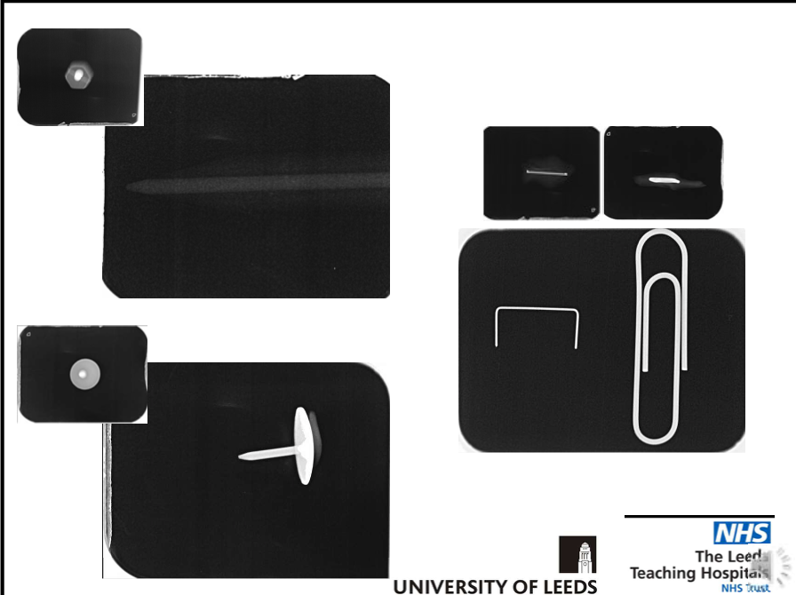
objects a-d are all cylinders, the bottom row are x rays
a- metallic- very high density- x ray Is radiopaque
b- air in the centre but metal around the outside-hence white line around cylinder on X-ray
c-dense centrally and low density around oursite- x ray is white block with peripheral area greyish(low density)
d-wood-thinner at the edges than it is centrally- edges attenuate fewer x rays hence radiograph will be lighter centrally and darker around the edges
metal(attenuates the most x rays) >wood>air(in terms of density hence white, then grey, then black)
Limitations of Viewing a 2D Image of 3D Object
• Appreciating overall shape of the object
– Must be viewed from several different positions/angles.
e.g
Limitations of Viewing a 2D Image of 3D Object
• Superimposition
- – Overlapping shadows of
different parts of an object or a separate object can obscure view
- – Causes limitation of information on location and shape of the object.
\n
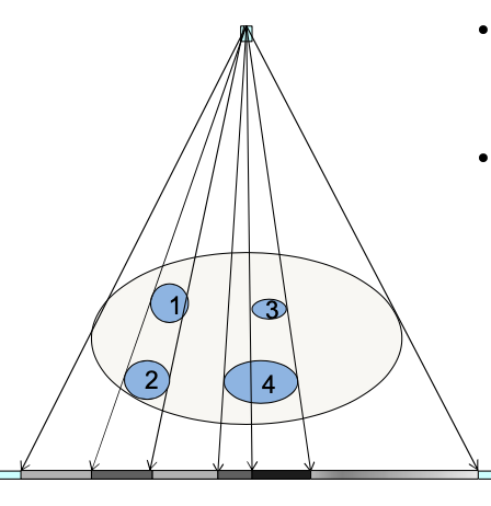
Limitations of Viewing a 2D Image of 3D Object
- No depth information: Is the object at position 1 or 2?
Object 3 overlaps object 4 but on the image you might not be able to tell(esp if object 4 is more dense)
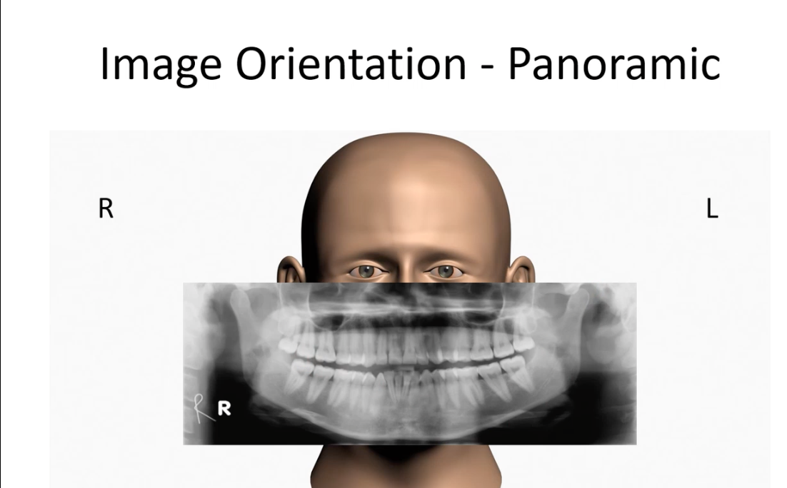
With X rays, its like you’re looking at patient- hence your left is their right and vice versa
• Radiography
– The techniques involved in producing radiographic images
• Radiology \n – The interpretation of medical imaging
• Radiation Protection
– The protection of patients and staff from the harmful effects of ionising radiation
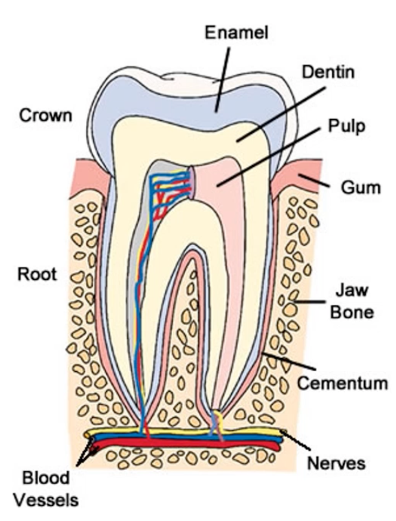
DENTAL ANATOMY
Dentine is of a lower density than enamel
Teeth sit in the alveolar bone, are separated from the bone by pdl
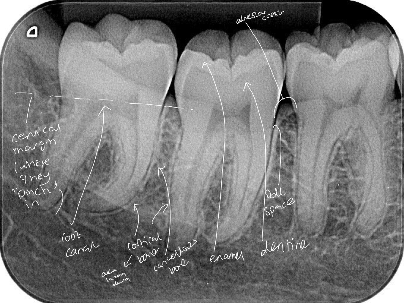
Lower right(mandible) quadrant- molars
High density enamel- radiopaque and white around the outside
Slightly lower density dentine-smooth grey
Root canal- soft tissue compared to enamel- doesn’t attenuate x rays as much- hence radiolucent(black) appearance
Black outline around tooth is the pdl space and next to it is a white line which is the bone. This is cortical bone, which is more dense than the cancellous bone seen between the teeth
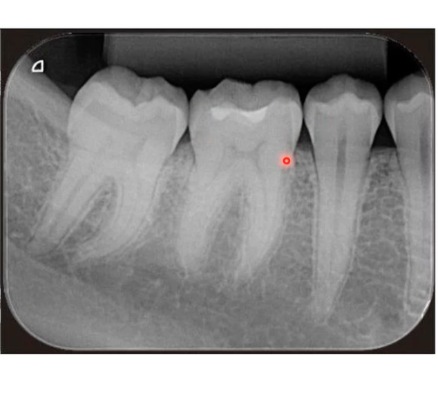
Lower right quadrant- two molars each with two roots, and two premolars, crown not as wide as molar and have a single tapering root
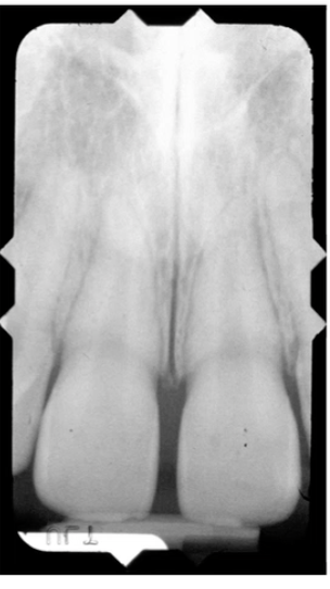
Maxillary central incisors- enamel is thinner on incisors compared to molars, broader canal and a single conical root
for mandibular teeth, apex/ root points upwards and crown points downwards- mandibular teeth are opposite rotation
Intraoral Radiographs
Periapical -lets you see crowns and roots
Bitewing- lots of crowns of both arches at the same time
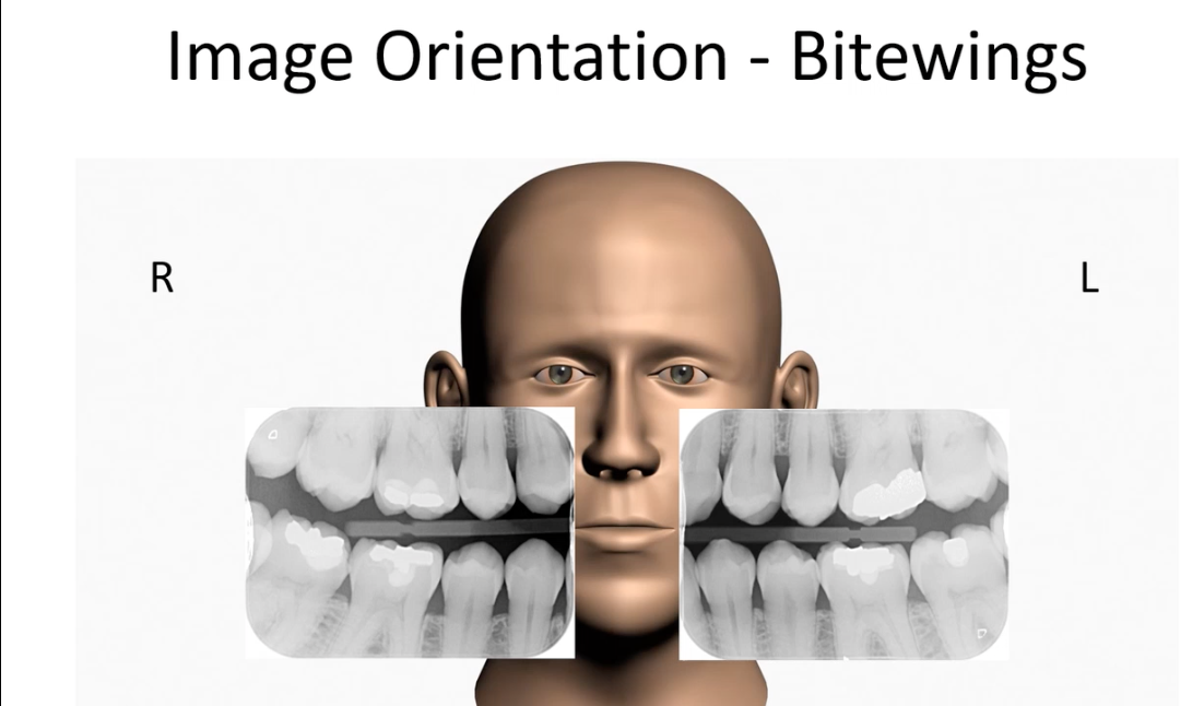
Right bitewing will have the molars on LHS and premolars on RHS
Left bitewing has molars on RHS and premolars LHS
Its like looking at patient head on, their molars are further back in their head(towards outside of image)
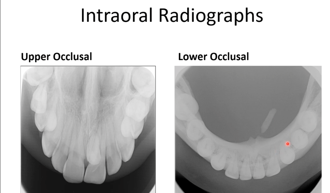 Upper-65 deg angle
Lower-90 deg angree
Taking x rays like this allow with localisation of teeth(i.e lingual, palatal etc)
On the lower occlusal image you can see a submandibular stone- in salivary glands preventing saliva production- had this been a panoramic or periapical image, you wouldn’t be able to tell the stone is lingual to the bone
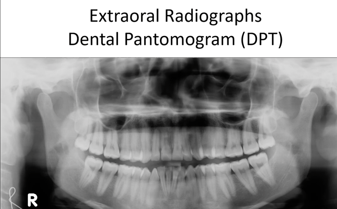
Image detector(and x ray beam) placed outside patients mouth- for intramural its placed inside
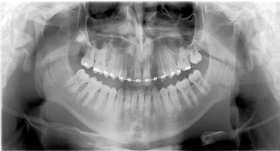
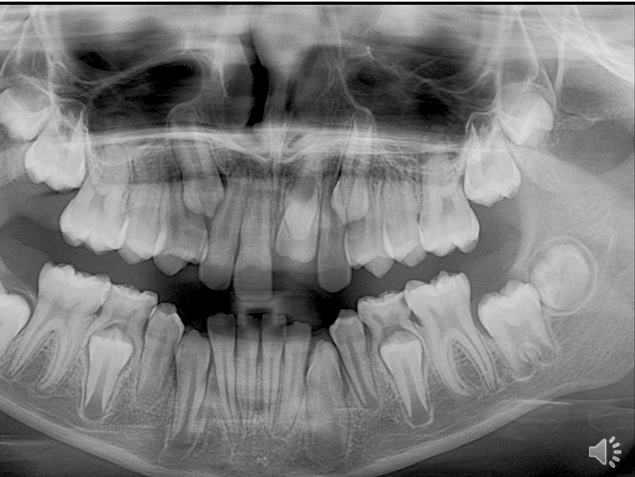
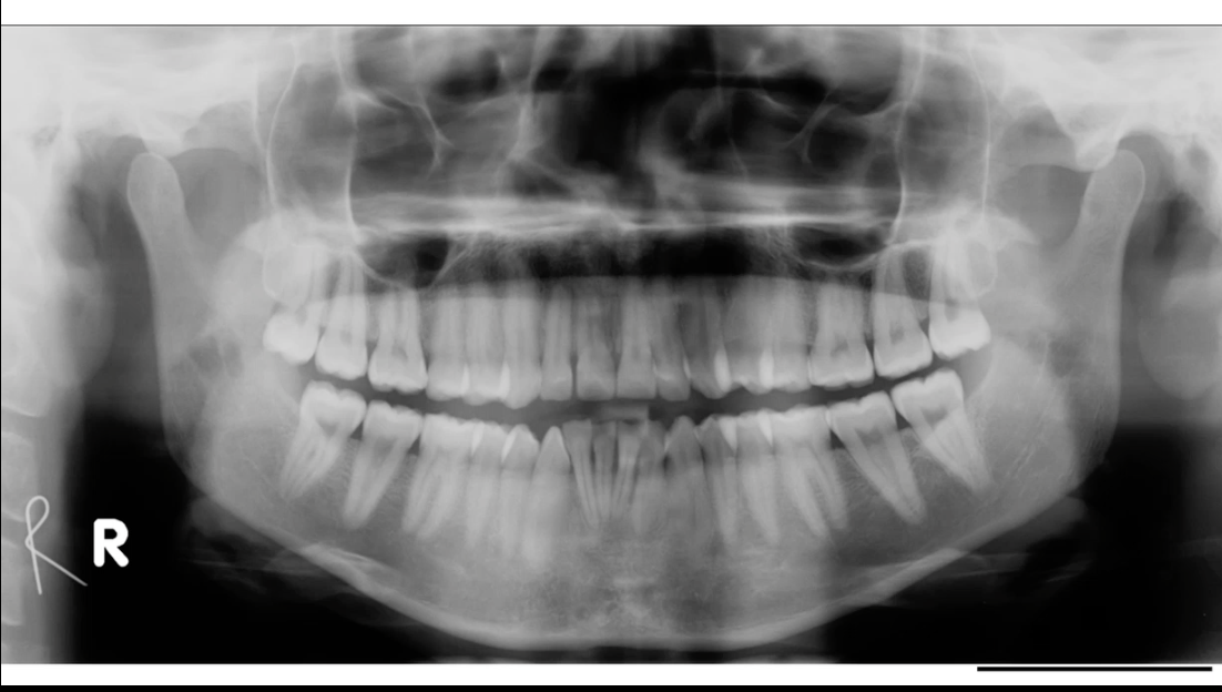
DPT- show full mandible and maxilla, roots, crowns can give good assessment of dentition
useful for patients with a large lesion in the bone as it can show a large area at once
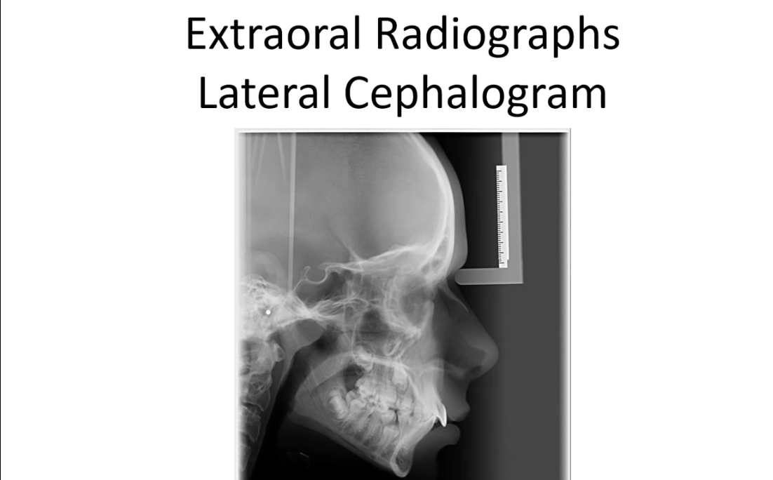
Lateral cephalograms- v useful in orthodontics as you can see relationship of mandible to maxilla to skull base(bone position and angles)
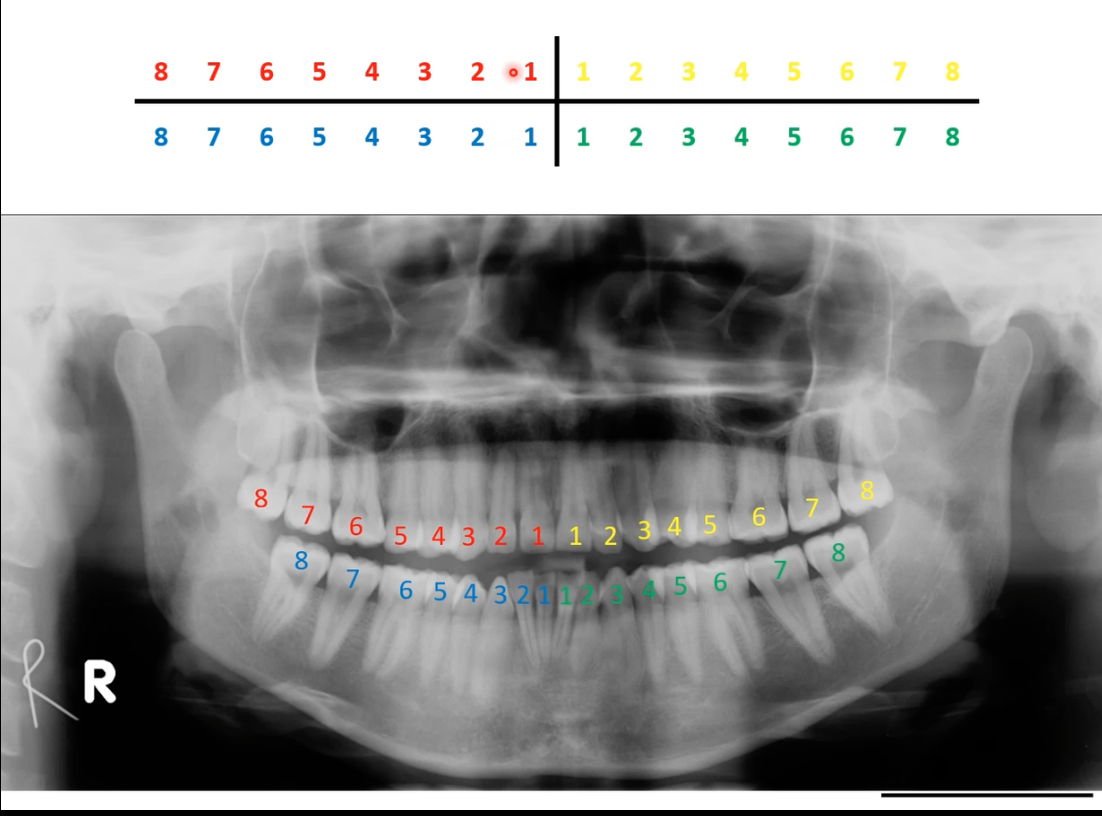
Charting - Palmer Notation
- Mouth divided into four quadrants
- Teeth are numbered 1-8 from central incisor to third molar
- ‘Letters and numbers system’
– Modification of Palmer
– LR3 to represent lower right canine.
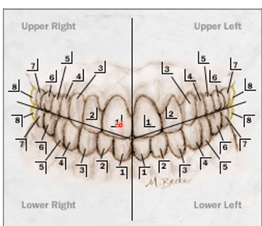
standard approach is to start in upper right quadrant-ul-lower l-lower right