Fiber Optic Cable Facts
Coaxial cable is commonly used to convey data, video, and voice signals in radio, television, and broadband internet applications.
This lesson covers the following topics:
Coaxial cable components
Comparison
Cable grade
Connectors
Coaxial Cable Components
Coaxial cable is built with the following components:
The inner conductor is made of a copper core. It carries the data signals.
The insulator surrounds the inner conductor and keeps the signal separated from the mesh conductor. It is made of PVC plastic.
The braided mesh conductor is a second physical channel and also functions as a ground. It is made of aluminum or tin-coated copper.
The sheath is made of PVC plastic and encases the cable, protecting it from external elements.
Comparison
Coaxial cable has the following advantages and disadvantages compared to other cable types:
Advantages | Disadvantages |
|---|---|
Advantages compared to other cable types include:
| Disadvantages compared to other cable types include:
|
Cable Grade
The table below describes the grade specifications of common coaxial cable.
Grade | Uses | Resistance Rating |
|---|---|---|
RG-59 | CCTV video systems; short cable lengths (less than 3 meters) are sometimes used for cable TV | 75 ohms |
RG-6 | Cable TV, satellite TV, and broadband cable internet | 75 ohms |
Because RG-6 can carry a higher-quality signal with much lower signal loss than RG-59, you should always use RG-6 cabling for coaxial cable implementations.
Connectors
The following table describes the most common type of connectors used with coaxial cable:
Connector | Description |
|---|---|
BNC | The BNC connector is molded onto the cable. It is used:
|
F-Type | The F-Type connector is crimped onto the cable using a special tool. It is used to:
|
Twisted pair cabling reduces interference when transmitting signals. It supports a wide range of fast, modern network standards.
This lesson covers the following topics:
Twisted pair cable components
Comparison
Categories
Rating
Twisted Pair Cable Components
Twisted pair cabling is composed of the following components.
Four pairs of copper wires carry the data signals. One wire in the pair carries a positive signal; the other carries a negative signal. Wires are twisted into pairs to reduce the effects of electromagnetic interference (EMI) and crosstalk.
Polyvinyl chloride (PVC) plastic insulation surrounds each copper wire.
An outer plastic sheath bundles the wires together and protects them.
Unshielded twisted pair (UTP) has only an outer plastic sheath. UTP cables are easier to work with and are less expensive than shielded cables.
Shielded twisted pair (STP) has a grounded outer copper shield around the entire wire bundle or around each wire pair. STP provides additional EMI protection, but costs considerably more than UTP.
T568A and T568B are two major wiring standards used in the networking industry. The Telecommunications Industry Association (TIA) /Electronic Industries Alliance (EIA) developed these standards that determine the order of the twisted pair wires placed in the RJ45 connectors when you are terminating a connection.
Comparison
Twisted pair cable has the following advantages and disadvantages compared to other cable types:
Advantages | Disadvantages |
|---|---|
|
|
Categories
The following table describes the unshielded twisted pair (UTP) cable categories and their specifications.
Even though cable categories may look physically similar, they are electrically different. Higher numbered cable categories have much faster transmission speeds because they use different wire gauges and have more wire twists per inch than lower numbered cable categories.
Category | Connector | Speed | Frequency | Description |
|---|---|---|---|---|
Phone cable | RJ11 | 10 Mbps | N/A | Used to connect a modem to a phone jack in a wall outlet to establish a dial-up internet connection. |
Cat 5 | RJ45 | 100 Mbps | 100 MHz | Supports up to 100 Mbps Ethernet. |
Cat 5e | RJ45 | 1000 Mbps | 100 MHz | Is similar to Cat 5 but provides better EMI protection. Supports gigabit Ethernet (gigabit connections require the use of all four twisted pairs). |
Cat 6 | RJ45 | 10 Gbps | 250 MHz | Limits 10 Gbps speeds to cable lengths less than 55 meters. |
Cat 6a | RJ45 | 10 Gbps | 500 MHz | Limits 10 Gbps speeds to cable lengths less than 100 meters. Provides additional shielding and tighter cable twists than standard Cat 6, which reduces (alien) crosstalk and makes it less susceptible to EMI. |
Cat 7 | RJ45 | 10 Gbps | 600 MHz | Has the strictest specifications for crosstalk and noise. In shielded only. |
Cat 7a | RJ45 | 10 Gbps | 1000 MHz | Offers exceptional noise immunity in addition to the strictest specifications for crosstalk and noise. In shielded only. |
Cat 8.1 | Class I: RJ45 | 25 Gbps | 2000 MHz | Rated for data transfers 250 times faster than Cat5. Is not compatible with Cat5e and Cat6 cables due to different connectors. In shielded only. |
Cat 8.2 | Class I: RJ45 | 40 Gbps | 2000 MHz | Rated for data transfers 400 times faster than Cat5. Is not compatible with Cat5e and Cat6 cables due to different connectors. In shielded only. |
Always use a special crimping tool to attach connectors to UTP cable.
Keep the following in mind when working with twisted pair cables:
Each type of UTP cable can be substituted for any category below it, but never for a category above. For example, Cat 6 can be substituted for a task requiring Cat 5e; however, neither Cat 5 nor Cat 3 should be used for the task.
Cat 5/5e/6/6a cables come with wires that have solid cores or stranded cores. Use solid core cables for longer runs inside walls or the ceiling; use stranded wires for drop cables where flexibility and frequent movement occurs.
Rating
Twisted pair cable can be rated differently for specific purposes in various construction applications.
Rating | Description |
|---|---|
Direct burial | Direct burial cable is designed to be buried directly in the ground.
|
General | Cables with general purpose rating are the minimum requirement in commercial installations including network patch cables.
|
Plenum | Plenum rated cable is laid in the plenum spaces of buildings and must meet rigorous fire safety standards. Air plenum spaces are the open areas above drop ceilings or below raised floors used for air circulation. Plenum cables are:
|
Riser | Riser rated cable is run between floors through open vertical shafts.
|
Twisted pair cables remain one of the primary ways that computers connect to a network.
This lesson covers the following topics:
Twisted pair cable connectors
Wiring standards
Ethernet pin specifications
Cable tips
Twisted Pair Cable Connectors
The table below describes the two types of connectors used with twisted pair cables.
Connector | Description |
|---|---|
RJ11 | The RJ11 connector:
|
RJ45 | The RJ45 connector:
|
Wiring Standards
The table below illustrates patch (also called straight through) and crossover cable wiring using T568A and T568B standards. These are the termination standards used by the internet backbone infrastructure, internet providers, and businesses.
Wiring | Description |
|---|---|
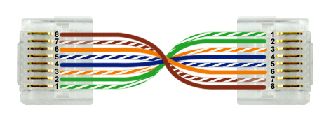
| Computers connect to the network through a hub or switch with a patch cable. Patch cables use the same wire configuration on each connector end. The most commonly used wiring configurations are:
It doesn't matter which standard you use as long as all cables use the same standard. This helps prevent confusion during troubleshooting. |
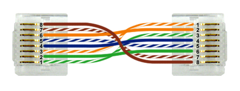
| Computers can connect directly to one another using a crossover cable. |
Ethernet Pin Specifications
Ethernet specifications use the following pins for communication:
Cat 5 Ethernet (100BASE-T) and below. (Tx is a pin used for transmitting and Rx is a pin used for receiving).
Pin 1: Tx+
Pin 2: Tx-
Pin 3: Rx+
Pin 4: Unused
Pin 5: Unused
Pin 6: Rx-
Pin 7: Unused
Pin 8: Unused
Cat 5e (1000BASE-T) and above. (Bi indicates the pin is used for both transmitting and receiving).
Pin 1: Bi+ D0
Pin 2: Bi- D0
Pin 3: Bi+ D1
Pin 4: Bi+ D2
Pin 5: Bi- D2
Pin 6: Bi- D1
Pin 7: Bi+ D3
Pin 8: Bi- D3
Cable Tips
Be aware of the following when making cables for Ethernet:
Use a crimping tool designed for RJ45 connectors to attach connectors to UTP cable. Most crimping tools include an integrated wire stripper that you can use to remove the outer sheath from the cable. This allows you to access the individual wires.
Use the appropriate punch-down tool when connecting UTP cabling to a punch-down block. To use a punch-down tool, position the UTP wire into a slotted post in the punch-down block. With the punch-down tool, press down on the top of the wire over the post.
Be sure to use the correct connector type. There are different connectors rated for solid or stranded core wires.
Keep the pairs twisted as much as possible up to the connector. This helps reduce crosstalk.
Be aware that making Cat 6 compliant cables is difficult. If you do not add the connectors exactly right, the cable will be capable of only 100 Mbps speeds. In most cases, it is easier to buy cables of the correct length than to try and make your own.
Fiber-optic cables deliver data, video, and voice services faster and more reliably than other cable systems.
This lesson covers the following topics:
Fiber-optic cable components
Comparison
Mode
Connectors
Fiber-optic Cable Components
A fiber-optic cable, also called an optical-fiber cable, is composed of the following components:
The central core carries the signal. It is made of plastic or glass.
The cladding maintains the signal in the center of the core as the cable bends.
The protective layer provides a stiff structure to prevent the cladding and central core from breaking.
The plastic sheath encases everything and protects the cable.
Comparison
Fiber-optic cabling offers the following advantages and disadvantages as compared to other cable types:
Advantages | Disadvantages |
|---|---|
Advantages of fiber-optic cable:
| Disadvantages of fiber-optic cable:
|
Mode
Multi-mode and single-mode fiber cables are distinct from each other and not interchangeable. The following table describes multi-mode and single-mode fiber cables.
Mode | Description |
|---|---|
Single-mode | Single-mode fiber-optic cable:
|
Multi-mode | Multi-mode fiber-optic cable:
|
Connectors
To connect computers using fiber optic cables, you need two fiber strands: one for transmitting and the other for receiving. Fiber optic cabling uses the following connectors:
Connector | Description |
|---|---|
ST Connector 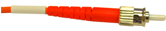 | An ST connector:
|
SC Connector 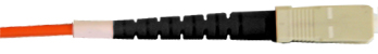 | An SC connector:
|
LC Connector 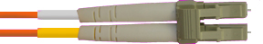 | An LC connector:
|
MT-RJ Connector 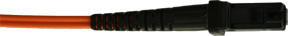 | An MT-RJ connector:
|