Network Layer: IPv6, NAT, and Middleboxes
The IPv4 Address Shortfall and Strategic Solutions
Depletion of the IPv4 Address Space:
The Internet Assigned Numbers Authority (IANA), overseen by the Internet Corporation for Assigned Names and Numbers (ICANN), officially allocated the final unallocated blocks of -bit IPv4 addresses in the year .
The exhaustion of unassigned address blocks created a fundamental architectural challenge regarding how emerging internet hosts, connected appliances, and expanding network services obtain and manage globally unique network identifiers.
Strategic Responses to IPv4 Address Exhaustion:
Approach 1 (Protocol Redesign): Design and standardize an entirely new iteration of the Internet Protocol characterized by an expansive address space capable of uniquely addressing every physical and virtual endpoint globally (the IPv6 specification).
Approach 2 (Address Space Reuse): Engineer technical workarounds and multiplexing frameworks that permit local networks to dynamically share and reuse the existing -bit IPv4 address pool without requiring ubiquitous, immediate infrastructure replacement (Network Address Translation).
Internet Protocol Version 6 (IPv6) Architecture
Addressing Capacity and Scaling:
IPv6 increases the address length from the -bit address space utilized in IPv4 to a -bit address space.
This transition expands the theoretical addressing volume from ( billion) distinct addresses to ( undecillion, or trillion trillion trillion) addresses, effectively removing practical limits on network endpoint addressing.
Header Streamlining and Architectural Adjustments:
The IPv6 base header is simplified to a fixed length of bytes, removing variable-length options from the base header to accelerate hardware-level packet processing and forwarding in core routers.
Directly Retained Header Fields:
Version: Identifies the Internet Protocol version ( instead of ).
Source Address: Expanded from bits to bits.
Destination Address: Expanded from bits to bits.
Repositioned and Renamed Header Fields:
Type of Service (IPv4) Traffic Class (IPv6): Designates packet priority and Quality of Service (QoS) markings.
Total Length (IPv4) Payload Length (IPv6): Indicates the length of the datagram following the fixed -byte base header rather than total packet length.
Protocol (IPv4) Next Header (IPv6): Identifies the transport-layer protocol (e.g., TCP, UDP) or chained extension headers (e.g., routing, security, fragmentation).
Time to Live / TTL (IPv4) Hop Limit (IPv6): Decremented by at every intermediary routing hop; datagram is discarded when the counter reaches zero.
New Header Fields:
Flow Label: A -bit field engineered to identify packets within designated "flows" needing specialized handling or non-default Quality of Service treatment (such as real-time audio or video streams).
Eliminated Header Fields:
Internet Header Length (IHL): Rendered redundant due to the invariant -byte IPv6 header format.
Identification, Flags, and Fragment Offset: Completely removed from the base header. In IPv6, intermediate routers no longer perform packet fragmentation; fragmentation is managed exclusively end-to-end by source hosts using optional Next Header extension blocks.
Header Checksum: Eliminated entirely to reduce router processing latency; error detection is delegated to link-layer and transport-layer checksum mechanisms.
Options and Padding: Shifted out of the primary header into modular extension headers pointed to sequentially by the Next Header field.

Transition Mechanics: Dual-Stack and Tunneling
The Transition Challenge:
Migrating the entire Internet from IPv4 to IPv6 requires software and hardware upgrades on millions of edge and core routers.
Coordinated, instantaneous global flag days are impossible due to administrative decentralization, equipment replacement costs, and operational downtime risks.
As a consequence, the global routing fabric must operate persistently over decades with heterogeneous topologies consisting of both IPv4-only and IPv6-capable devices.
Foundational Mechanics of Tunneling:
Definition: A network architecture mechanism engineered to transmit packets belonging to a foreign or unsupported network protocol across an intervening network topology that does not natively route that protocol.
Packet Encapsulation Mechanism: The sender nests an entire protocol datagram within the payload field of an outer datagram compatible with the intermediate network.
Common Implementations:
IPv6-in-IPv4 Tunneling: Encapsulating an IPv6 packet as the payload inside an IPv4 packet to traverse an IPv4-only transit infrastructure.
Virtual Private Networks (VPNs): Encapsulating private, authenticated intranet traffic inside standard public Internet datagrams to allow remote users to interact securely as if directly wired into a local private network.
SSH Tunneling: Packaging arbitrary application protocol payloads inside an encrypted Secure Shell (SSH) transport stream.
IPv6-in-IPv4 Tunneling Operation:
Topology Context:
Source Host operates native IPv6.
Edge Router operates dual-stack functionality (supporting both IPv6 and IPv4).
Transit Routers and operate exclusively as IPv4 routers.
Egress Router operates dual-stack functionality (IPv6 and IPv4).
Destination Server operates native IPv6.
Step-by-Step Packet Traversal Lifecycle:
Origin Segment (): Host formats a pure IPv6 datagram containing Flow Label , Source IP Address , Destination IP Address , and application payload, transmitting it over an IPv6 local link to Dual-Stack Router .
Encapsulation at Ingress (): Router examines its routing table, determines that the path to Destination crosses an IPv4 network, and encapsulates the entire IPv6 datagram into an IPv4 datagram payload.
The outer IPv4 header is configured with Source IP and Destination IP .
Intermediate Transit (): Core routers and evaluate solely the outer IPv4 header, routing the packet as standard IPv4 traffic through the cloud without parsing or acknowledging the nested IPv6 payload.
Decapsulation at Egress (): Dual-Stack Router receives the IPv4 datagram, identifies that it contains an encapsulated IPv6 payload, strips the outer IPv4 header, and exposes the original IPv6 datagram.
Final Delivery (): Router forwards the original IPv6 datagram (Source , Destination , Flow ) over the native IPv6 link to destination Host .
IPv6 Adoption Realities and Deployment Metrics
Adoption Velocity and Challenges:
Despite standardization occurring over years ago, IPv6 transition remains gradual rather than complete.
The survival and efficacy of alternative stopgap mechanisms (principally NAT) have substantially diminished economic incentives for enterprise networks to incur the capital expenditures necessary for total IPv6 conversion.
Adoption Metrics:
Client Traffic Volume: Approximately of client search queries arriving at Google infrastructure are conducted over native IPv6 connections.
Government Enterprise Adoption: Approximately of all United States federal government domain registries possess verified IPv6 capability.
Network Address Translation (NAT) Architecture and Functionality
Core Operational Principle:
Network Address Translation (NAT) maps one IP address space into another by rewriting the source or destination IP addresses and transport-layer port numbers within packet headers as they transit an edge routing device.
Enables an entire local area network (LAN) containing dozens to thousands of physical or virtual hosts to share a single public IPv4 address (or a small allocated subnet of public addresses) when interacting with external Internet hosts.
Reserved Private IP Address Spaces (RFC 1918):
Three address ranges are globally designated for non-routable private networks and are discarded by default by public Internet backbone routers:
Class A Block:
10.0.0.0/8(address span:10.0.0.0through10.255.255.255, yielding host addresses).Class B Block:
172.16.0.0/12(address span:172.16.0.0through172.31.255.255, yielding host addresses).Class C Block:
192.168.0.0/16(address span:192.168.0.0through192.168.255.255, yielding host addresses).Any home, enterprise, or institution can deploy these identical private subnets simultaneously without coordination or conflict, because their validity is constrained strictly within local network boundaries.
Motivations and Operational Advantages of NAT:
Address Conservation and Reusability: Local devices multiplex communication through just one globally unique public IP leased from an upstream Internet Service Provider (ISP).
Internal Administrative Flexibility: Network engineers can freely change internal private host addresses without registering modifications with external routing registries or notifying outside endpoints.
External Administrative Independence: An enterprise can switch upstream ISPs without renumbering or updating IP configurations across internal client hosts.
Edge Security and Concealment: Internal network infrastructure is protected from unsolicited incoming probes, scans, or exploits because private host addresses are not directly visible or globally addressable from the public Internet.
NAT Operational Mechanics and Implementation
Responsibilities of a NAT-Enabled Router:
Outgoing Packet Rewriting: For every outbound datagram originating from a private host, substitute the private
(Source IP Address, Source Port Number)pair with the public(NAT WAN IP Address, NAT-Assigned Port Number).Translation State Tracking: Maintain a dynamic NAT Translation Table that indexes every active conversation by recording corresponding mappings between LAN side addresses/ports and WAN side addresses/ports.
Incoming Packet Rewriting: For every incoming response datagram arriving at the WAN interface, parse the destination port number, look up the corresponding internal entry in the translation table, and replace the destination header parameters with the private
(Source IP Address, Source Port Number)prior to internal forwarding.
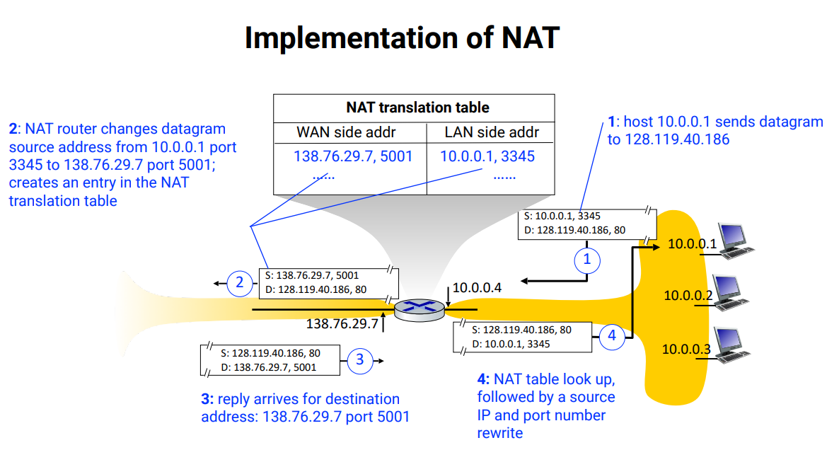
Detailed Step-by-Step Translation Example:
Environment Parameters:
Internal Private Subnet:
10.0.0.0/8Internal Client Host:
10.0.0.1NAT Router Internal Gateway Interface:
10.0.0.4NAT Router Public External WAN Interface:
138.76.29.7External Web Server:
128.119.40.186listening on port80Execution Lifecycle:
Internal Datagram Generation: Client
10.0.0.1initiates an HTTP request from dynamic source port3345targeted to128.119.40.186:80. The IP packet hasSource: 10.0.0.1, Port 3345andDestination: 128.119.40.186, Port 80.NAT Gateway Interception and Mapping: The packet arrives at gateway interface
10.0.0.4. The NAT router allocates an unused temporary port on its WAN interface (e.g., port5001).The router writes a new state mapping into the NAT Translation Table:
WAN Side (138.76.29.7, 5001) <-> LAN Side (10.0.0.1, 3345).The router modifies the datagram's header:
Source IPbecomes138.76.29.7andSource Portbecomes5001.The modified packet is emitted into the public WAN. The remote web server perceives the source of the communication to be
138.76.29.7:5001.
External Response Arrival: The web server constructs an HTTP response with
Source: 128.119.40.186, Port 80andDestination: 138.76.29.7, Port 5001, transmitting it across the public Internet back to the router's WAN IP.Inbound Table Lookup and Demultiplexing: The NAT gateway inspects the destination port
5001, matches it to the recorded NAT translation table record, and finds internal host10.0.0.1:3345.The router rewrites the destination IP address to
10.0.0.1and the destination port to3345.The datagram is dispatched onto the internal LAN, reaching host
10.0.0.1transparently.
Architectural Controversies and Second-Order Effects of NAT
Architectural Critique and Compromises:
Workaround vs. Long-Term Solution: From a purist architectural perspective, address shortages are intended to be resolved through the formal expansion of the network layer address space (IPv6) rather than stateful address mutation.
Violation of the End-to-End Principle:
The core design philosophy of the Internet asserts that intermediate routing infrastructure should execute simple, stateless packet forwarding based solely on layer- headers, while connection state, session tracking, and application logic must reside exclusively at the communicating end hosts.
NAT alters this paradigm: intermediate routers inspect, parse, and rewrite transport-layer (layer-) TCP/UDP port fields, violating layer separation and creating fragile intermediate network state.
The Inbound Service Discovery Problem:
Because hosts behind a NAT router lack public IP addresses and do not register static entries in external translation tables, external clients cannot natively initiate inbound TCP or UDP connections to servers, peer-to-peer (P2P) nodes, or VoIP clients situated inside a private LAN.
Overcoming this requires complex application-level workarounds, including Universal Plug and Play (UPnP), port forwarding, Interactive Connectivity Establishment (ICE), Session Traversal Utilities for NAT (STUN), and Traversal Using Relays around NAT (TURN).
Middleboxes in Modern Network Architectures
Formal Middlebox Definition (RFC 3234):
A middlebox is defined as any intermediary functional device positioned along the data path between a communicating source host and destination host that executes functions other than the standardized, conventional routing behavior expected of an IP router (namely, longest-prefix match destination forwarding).
Prevalence and Middlebox Taxonomies:
Middlebox devices are pervasive across modern edge, aggregation, and core topologies, including home networks, mobile cellular carrier cores, enterprise networks, local/regional ISPs, national/global transit ISPs, datacenter networks, and content provider networks.
Key Classes of Middleboxes:
Network Address Translators (NAT): Widely deployed across home gateways, mobile broadband gateways, and corporate enterprise edges to perform address conservation and subnet shielding.
Firewalls and Intrusion Detection Systems (IDS): Installed at enterprise boundaries to filter packets, enforce deep-packet security rules, drop malicious payloads, and block unauthorized traffic ports.
Load Balancers: Deployed within cloud datacenters, content delivery architectures, and enterprise server farms to distribute incoming request flows across pools of replicated back-end servers.
Network Function Virtualization (NFV): A modern operational paradigm that decouples proprietary middlebox hardware appliances from their software functions, executing routing, load balancing, filtering, and caching as virtualized software components instantiated on commodity servers.
The Internet Hourglass Model and Protocol Evolution
The Classical "Thin Waist" Organizing Principle:
Top Layers (High Protocol Diversity): Application Layer contains rich variety (e.g., HTTP, SMTP, QUIC, DASH, RTP).
Middle Sub-Layer: Transport Layer provides host-to-host process communication channels (TCP, UDP).
The Central Thin Waist: The Network Layer consists of a single universal protocol: the Internet Protocol (IP).
Every connected device, node, switch interface, and host across the global network must implement IP to achieve internetworking.
The operational simplicity and stability of the invariant IP waist historically allowed innovation to flourish independently in the application/transport tiers above and in physical transmission media below.
Bottom Layers (High Transmission Diversity):
Link Layer incorporates diverse protocols (Ethernet, Wi-Fi, Bluetooth, Point-to-Point Protocol / PPP, Packet Data Convergence Protocol / PDCP).
Physical Layer spans varied media (copper twisted pair, radio frequency spectra, optical fiber conduits).
Hourglass Waist Expansion in the Modern Era:
As the global network has matured into its "middle age," the once-minimal thin waist of the Internet has expanded.
The proliferation of ubiquitous middleboxes—such as stateful NAT gateways, deep-packet firewalls, NFV pipelines, and layer-/layer- load balancers—has compromised the pure simplicity of the IP layer, tightly coupling network forwarding to transport and application layer attributes.