CISCO 2
MODULE 1
1.1 CONFIGURE A SWITCH WITH INITIAL SETTINGS
1.1.1 SWITCH BOOT SEQUENCE
5-step boot sequence:
step 1: switch loads the power-on self-test (POST) program (stored in ROM).
POST checks the CPU subsystem
tests the CPU, DRAM, and the portion of teh flash device that makes up the flash system
step 2: switch loads the boot loader software
boot loader is a small program stored in ROM
runs immediately after POST successfully completes
step 3: boot loader performs low-level CPU initialization
controls where physical memory is mapped, the quantity of memory, and its speed
step 4: boot loader initializes the flash system on the system board
step 5: boot loader locates and loads a default IOS operating system software image into memory and gives control of teh switch over to the IOS
looks for the IOS → loads IOS into memory (RAM) → lets IOS take over the switch
1.1.2 THE BOOT SYSTEM COMMAND
switches attempts to automatically boot using information in the BOOT environment variables
if this variable is not set, the switch tries to load and execute the first executable file it can find
IOS loads the saved settings from the config.text file found in the startup-config file
stored in flash memory
boot system command:
Command | Definition |
boot system | main comand |
[storage-device]: | storage device |
[directionary-path/] | path to the file system |
[filename.bin] | IOS file name |
example:
S1(config)# boot system flash:c2960-lanbasek9-mz.150-2.SE/c2960-lanbasek9-mz.150-2.SE.bin
check each word or thing to know which one is which using the comments
1.1.3 SWITCH LED INDICATORS

Cisco Catalyst switches have several status LED indicator lights
to quickly monitor switch activity and performance
Mode Button is used to toggle through port status, port duplex, port speed, and if supported, the Power over Ethernet (PoE) status of the port LEDs
LEDs | COLOR | MEANING |
1SYS (SYSTEM) |
|
|
|
| |
|
| |
2 RPS (REDUNDANT POWER SYSTEM) |
|
|
|
| |
|
| |
|
| |
|
| |
3 STAT (PORT STATUS) |
|
|
|
| |
|
| |
|
| |
|
| |
|
| |
4 DUPLEX |
|
|
|
| |
5 SPEED |
|
|
|
| |
|
| |
6 PoE (POWER OVER ETHERNET) |
|
|
|
| |
|
| |
PORT LED (WHEN PoE IS SELECTED) |
|
|
|
| |
|
| |
|
| |
|
|
1.1.4 RECOVERING FROM A SYSTEM CRASH
boot loader provides access into the switch if the operating system cannot be used
missing or damaged system files
boot loader has a comman-line
provides access to the files stored in flash memory
by default, switch attempts to automatically boot up by using information in the BOOT environmental variable
boot loader can be accessed through a console connection:
step 1: connect a PC by console cable to the switch console port
configure terminal emulation software to connect to the switch
step 2: unplug the switch power cord
step 3: Reconnect the power cord to the switch
within 15 seconds, press and hold down the mode button while the system LED is still flashing green
step 4: continue pressing the mode button until the system LED turns briefly amber and then solid green
release the mode button after
step 5: boot loader switch: prompt appears in the terminal emulation software on the PC
type help or ? at the boot loader prompt to view a list of available commands
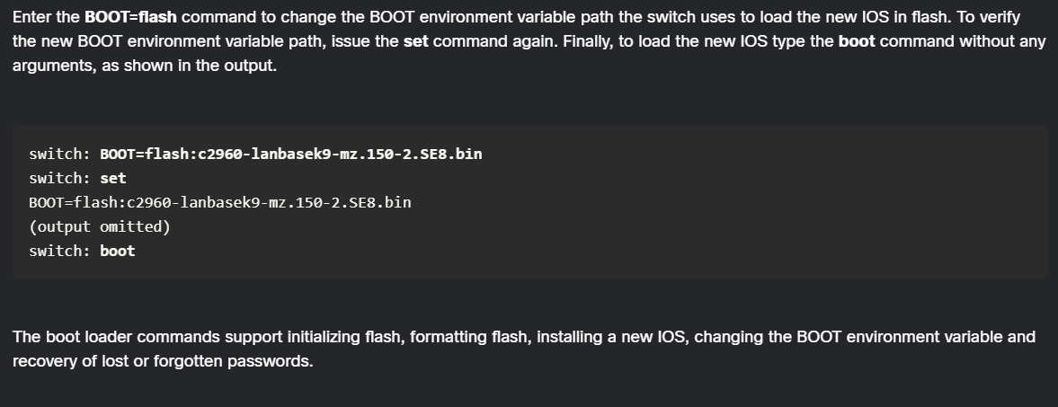
to view the path of the switch BOOT environment variable type the set command. then initialize the flash file system using the flash_init command to view the current files in flash

1.1.5 Switch Management Access
Purpose: To manage a switch from a remote computer, it must have a Switch Virtual Interface (SVI).
Requirements:
IPv4 address and subnet mask or an IPv6 address and prefix length.
Default Gateway: Necessary to manage the switch from a different network (remote network).
Concepts:
SVI: A virtual interface inside the switch's software, not a physical plug you can touch.
Default Gateway: The "exit door" a device uses to send information to other networks.
1.1.6 Switch SVI Configuration Example
Best Practice: Use a VLAN other than the default (VLAN 1) for management, such as VLAN 99.
Step 1: Configure Management Interface:
configure terminal: Enter global settings mode.interface vlan 99: Enter the virtual "management door" settings.ip address 172.17.99.11 255.255.255.0: Assign an IPv4 address.ipv6 address 2001:db8:acad:99::11/64: Assign an IPv6 address.no shutdown: Turn the interface on.end: Return to the main screen.copy running-config startup-config: Save your work.
Step 2: Configure Default Gateway:
ip default-gateway 172.17.99.1: Tells the switch how to find other networks for IPv4.Note: IPv6 does not need this command because it gets route info automatically from Router Advertisement (RA) messages.
Step 3: Verify Configuration:
show ip interface briefandshow ipv6 interface brief: Display the status of physical and virtual interfaces.The SVI will only show as "up/up" (working) if the VLAN exists and at least one physical port is active on that VLAN.
Switch Booting and Hardware (No Section Number)
The Boot Command:
boot system flash:/[path]/[filename]tells the switch which operating system to load.LED Indicators: The front of a Cisco switch has several lights:
SYST (System): Overall status.
RPS (Redundant Power Supply): Backup power status.
STAT (Status): Port activity.
DUPLX (Duplex): Shows if ports are full or half-duplex.
SPEED: Port speed.
PoE: Power over Ethernet status.
Boot Loader Mode: Used if the switch software fails:
flash_init: Wakes up the storage device.dir flash:: Lists files in the switch's memory.set: Shows environmental settings (like which file to boot).boot: Manually starts the system software.
1.2 CONFIGURE SWITCH PORTS
1.2.1 Duplex Communication
Full-Duplex: Devices can send and receive data at the same time, which is highly efficient and eliminates collisions.
Half-Duplex: Only one device can talk at a time. It is unidirectional and often results in collisions.
Key Concept: Microsegmentation creates a collision-free environment by giving each device its own private lane on the network.
1.2.2 Configure Switch Ports at the Physical Layer
Manual Configuration: You can force a port to a specific speed or duplex mode:
interface FastEthernet 0/1: Select a port.duplex full: Set to both talk and listen at once.speed 100: Set the speed to 100 Mbps.
Auto-negotiation: The default setting where devices "discuss" and agree on the best speed/duplex. This can fail and cause mismatches.
Fiber-optic ports: These (like 1000BASE-SX) only work at one speed and are always full-duplex.
1.2.3 Auto-MDIX
Purpose: Automatically detects if you used the wrong type of Ethernet cable (straight-through vs. crossover) and makes it work anyway.
Requirement: Port speed and duplex must be set to "auto" for this to work.
Command:
mdix auto(within interface mode).
1.2.4 & 1.2.5 Switch Verification Commands
show interfaces [id]: Deep dive into a port's status and errors.show startup-config: Settings saved for the next restart.show running-config: Settings currently active in memory.show flash: View files in the switch's storage.show mac-address-table: Shows which physical device is plugged into which port.
1.2.6 & 1.2.7 Network Access Layer Issues and Errors
Interface Status Codes:
Up/Up: Interface is operational.
Up/Down: Hardware is okay, but there's a software or "agreement" problem (like a protocol mismatch).
Down/Down: Cable is likely unplugged or damaged.
Admin Down: Someone manually typed
shutdownon that port.
Error Types:
Runts: Packets smaller than 64 bytes (too tiny).
Giants: Packets larger than 1,518 bytes (too big).
CRC (Cyclic Redundancy Check): Data was damaged in transit, often by bad cables or electrical noise.
Collisions: Two devices talked
at once (normal in half-duplex).
Late Collisions: Collisions that happen late in the transmission; usually caused by a cable that is too long or a duplex mismatch.
1.3 SECURE REMOTE ACCESS
1.3.1 Telnet vs. 1.3.2 SSH
Telnet (Port 23): Sends usernames and passwords in plaintext. Anyone watching the network can see them.
SSH (Port 22): Uses encryption (scrambling the data) to provide a secure remote connection.
SSH Requirement: The switch software must have "k9" in its name (e.g.,
c2960-lanbasek9-m), which means it supports security features.
1.3.5 Verify SSH
show ip ssh: Confirms if SSH is enabled and what version is running (Version 2.0 is preferred).show ssh: Displays who is currently connected to the switch.
1.4 BASIC ROUTER CONFIGURATION
1.4.1 Configure Basic Router Settings
Setup Commands:
hostname R1: Name the device.enable secret class: Set a password for the most powerful settings.line console 0: Secure the physical plug-in port.line vty 0 4: Secure the "virtual" remote access lines.service password-encryption: Scramble passwords so they can't be read in the config file.banner motd #...#: A legal warning message shown at login.
1.4.2 Configure Router Interfaces
Steps to make a router port work:
Assign an IP address (
ip address ...).Add a Description (e.g.,
description Link to LAN 1) to help you identify it later.Activate it with
no shutdown(router ports are off by default).
1.4.3 IPv4 Loopback Interfaces
Purpose: A "fake" software interface that is always "up". It is used for testing and making sure the router's internal software is healthy.
Command:
interface loopback 0followed by an IP address.
1.5 VERIFY DIRECTLY CONNECTED NETWORKS
1.5.1 - 1.5.5 Router Verification
show ip interface brief: A quick summary of port status.show ipv6 interface [id]: Shows link-local addresses (starting with FE80) and multicast groups.show ip route: Shows the Routing Table, which is the router's "map" of where to send data.'C': A network directly plugged into the router.
'L': The router's own specific IP address on that network.
ping: Sends a "test pulse" to another device. Successful tests show five exclamation points (!!!!!).
1.5.6 Filter Show Command Output
You can use the pipe (|) symbol to search through long lists of information.
section: Shows an entire block of settings (e.g.,
section line vty).include: Shows only lines with a specific word.
exclude: Hides lines with a specific word.
begin: Starts the output from a specific word.
1.5.8 Command History Feature
The router remembers the last 10 commands you typed.
Shortcuts: Use Ctrl+P (Previous) or the Up Arrow to see older commands.
Resize: Use
terminal history size [number]to remember more commands during your current session.
MODULE 2
2.1 FRAME FORWARDING
2.1.1 Switching in Networking
The Big Picture: Switching is the universal method for moving "packages" of data, called frames, across a network.
Term - Ingress: This refers to the specific "plug" or port where a frame enters the switch.
Term - Egress: This describes the port that the frame will use when leaving the switch to go to its next destination.
The Switch's Logic: A switch is "smart" because it keeps a Port Table. This is like a mailroom directory that associates a specific device's ID with a specific port number.
Key Rule: To prevent confusion and loops, an Ethernet frame will never be sent back out of the same port it arrived on.
2.1.2 The Switch MAC Address Table
Term - MAC Address: Every piece of network hardware has a unique "digital fingerprint" or ID called a Media Access Control address.
Term - CAM Table: Switches store their address book in a high-speed memory area called Content Addressable Memory (CAM). Because of this, the MAC address table is often called the CAM table.
The Learning Process: For a switch to know where to send a frame, it must first learn which devices live on which ports. It does this by recording the Source MAC address (the sender's ID) of every incoming frame and the port it entered.
2.1.3 The Switch Learn and Forward Method
Every time a frame enters a switch, it follows a two-step process:
Step 1: Learn (Checking the Sender): The switch looks at the sender's ID (Source MAC). If it is new, the switch adds it to the table. If it is already known, the switch refreshes a 5-minute timer to keep the entry active.
Step 2: Forward (Checking the Receiver):
Term - Unicast: A message meant for one specific receiver. If the switch knows where the receiver is, it sends the frame directly to that port.
Term - Unknown Unicast / Flooding: If the switch doesn't know where the receiver is, it acts like it's "shouting" and sends the frame out to every port except the one it came in on.
Term - Broadcast/Multicast: Messages intended for a group or everyone are also "flooded" to all ports.
2.1.4 Video - MAC Address Tables on Connected Switches
(Summary of the step-by-step example provided in our conversation)
The Scenario: PC-A sends data to PC-B through two switches (S1 and S2).
Initial Discovery: Because S1 doesn't know where PC-B is yet, it floods the frame. S2 receives this, learns where PC-A is located (by looking at the source ID), and then floods the frame again to its own ports.
The Reply: When PC-B sends a message back, the switches look at the source, finally learn PC-B's location, and can now send all future messages directly to the correct ports without "shouting" to everyone.
2.1.5 Switching Forwarding Methods
Term - ASICs: Decisions are made by Application-Specific Integrated Circuits, which are specialized computer chips designed to move data at lightning speeds without slowing down the network.
Method 1 - Store-and-Forward: The switch waits to receive the entire frame before deciding where to send it.
Method 2 - Cut-Through: The switch starts sending the frame as soon as it sees the receiver's address, even before the whole frame has arrived.
2.1.6 Store-and-Forward Switching
Term - CRC & FCS: While the frame is in the "waiting room," the switch performs a Cyclic Redundancy Check (CRC). It checks a mathematical "security seal" called the Frame Check Sequence (FCS) to ensure the data wasn't damaged during travel. If it’s broken, the switch drops it.
Term - Automatic Buffering: This is a "holding area" in memory. It allows the switch to handle different speeds—for example, taking data from a slow 100 Mbps port and smoothly moving it to a fast 1 Gbps port.
2.1.7 Cut-Through Switching
Term - Latency: This is the tiny "lag" or delay in moving data. Cut-through switching has very low latency, making it ideal for high-performance computing.
Term - Fragment-Free: A smarter version of cut-through that waits for the first 64 bytes to arrive. This ensures the frame isn't a "fragment" caused by a data crash before sending it along.
The Risk: Because it doesn't check for errors first, this method can accidentally forward "trash" (corrupted data), which can clog up the network.
2.2 COLLISIONS AND BROADCAST DOMAINS
2.2.1 Collision Domains
Term - Collision Domain: A section of the network where two devices might try to "talk" at the same time, causing their data to crash or "collide".
Term - Full-Duplex: This is like a two-lane highway where data can go both ways at once. Modern switches use this to eliminate collisions.
Term - Half-Duplex: Like a walkie-talkie where only one person can talk at a time. If a switch connects to an old device (like a "hub"), it must use this slower, crash-prone method.
2.2.2 Broadcast Domains
Term - Broadcast Domain: A group of connected switches where a "shout" (Broadcast) from one device is heard by all others.
The Problem: Too many "shouts" from too many devices can result in congestion, which slows down the whole network.
Term - Router: Only a Router (a device that connects different networks) can stop a broadcast from spreading into other parts of the larger network.
2.2.3 Alleviate Network Congestion
Switches have special features to keep the network from getting "clogged":
Fast Port Speeds: Ports can handle massive amounts of data, with some supporting up to 100 Gbps.
Fast Internal Switching: The switch uses high-speed "internal highways" (buses) to handle many conversations at once.
Large Frame Buffers: These are large memory "waiting rooms" that store data during busy spikes so it isn't lost.
Term - High Port Density: This means putting many ports (like 24 or 48) on a single switch. This is cheaper and keeps traffic local so it doesn't have to travel across the whole network.
MODULE 3
3.1 VLAN Concepts
3.1.1 VLAN Definitions
A VLAN (Virtual Local Area Network) allows a network administrator to take one physical piece of equipment (a switch) and digitally split it into several smaller, private networks. This provides segmentation, which is like building virtual walls between departments—such as IT, HR, or Sales—so they can operate as if they are on their own independent cables, even if they are all plugged into the same box. These connections are logical, meaning they are based on software settings rather than the physical location of the user.
3.1.2 Benefits of a VLAN Design
Smaller Broadcast Domains: In networking, a "broadcast" is like a loud announcement sent to every computer. VLANs break one giant noisy room into smaller rooms, so only the people in your specific group hear your announcements, which makes the network faster.
Improved Security: Sensitive data, like payroll, can be put in a private VLAN so that guests or other departments cannot access it.
Improved IT Efficiency: Admins can group people with similar needs together and give the groups easy-to-understand names like "Faculty" or "Student".
Reduced Cost: You don't need to buy separate hardware for every department; you use your existing equipment more efficiently, saving money on upgrades.
3.1.3 Types of VLANs
Default VLAN: On Cisco switches, this is VLAN 1. Out of the box, every plug (port) on the switch belongs to this group. It also handles basic background management tasks.
Data VLAN: These are the "workhorse" networks used for everyday user tasks like sending emails or browsing the web.
Native VLAN: This is a special lane used for "untagged" traffic—data that travels across a trunk highway without a digital label.
Management VLAN: A private lane used exclusively by IT staff to log in and manage the switch settings from a distance.
Voice VLAN: A high-priority lane reserved for digital desk phones (VoIP) to ensure that phone calls stay clear and don't lag when the network is busy.
3.2 VLANs in a Multi-switched Environment
3.2.1 Defining VLAN Trunks
A Trunk is a high-speed "highway" link between two network devices (like two switches) that can carry traffic for multiple VLANs at the same time. It allows your virtual networks to stretch across the entire building, so the "Sales" team on the first floor can talk directly to the "Sales" team on the third floor without needing a router.
3.2.2 Network without VLANs
In a traditional network without VLANs, every time a computer sends a broadcast message (a "shout" to find something), every single other computer on the network hears it. This creates one massive, inefficient "broadcast domain" where every device is constantly distracted by everyone else's announcements.
3.2.3 Network with VLANs
When VLANs are used, the network is divided into smaller groups. Now, when a "Faculty" computer sends a broadcast, the switch is smart enough to only send that message to other "Faculty" ports. This keeps the rest of the network quiet and efficient.
3.2.4 VLAN Identification with a Tag
since a trunk highway carries many VLANs, the switch uses Tagging (the 802.1Q standard) to keep them organized. it adds a tiny 4-byte digital label to the data.
Tag Field | Description |
Type | 2-byte value identifying the frame as tagged. |
User priority | 3-bit value that helps the switch know which data is most important |
CFI (Canonical Formal Identifier) | 1-bit indentifier used for older network types |
VLAN ID (VID) | 12-bit number identifying exactly which virtual network the data belongs to |
3.2.5 Native VLANs and 802.1Q Tagging
The Native VLAN is the group assigned to any data that arrives at a trunk highway without a digital label (untagged). By default, Cisco switches use VLAN 1 as the native VLAN. If a switch receives untagged traffic, it automatically places it into this group.
3.2.6 Voice VLAN Tagging
Digital phones often have a small switch built inside them. You can plug a computer into the phone, and then plug the phone into the wall. The switch sends a message to the phone telling it to "tag" all voice traffic with a priority label so your phone calls aren't interrupted by your computer's internet traffic.
3.2.7 Voice VLAN Verification Example
IT professionals use the command show interfaces fa0/18 switchport to double-check that a single wall plug is correctly handling two different groups at once: one for the computer's data (e.g., VLAN 20) and one for the phone's voice (e.g., VLAN 150).
3.3.1 VLAN Ranges on Catalyst Switches
Cisco switches can support over 4,000 VLANs.
Normal Range (1 - 1005): Used in most small to medium businesses. VLANs 1 and 1002–1005 are created automatically and cannot be deleted.
Extended Range (1006 - 4094): Used by very large global companies or internet service providers.
3.3.2 VLAN Creation Commands
To create a new virtual group, you enter the switch's settings and type vlan [number] to create it, and then name [label] to give it a descriptive name (like "student" or "payroll").
Task | IOS Command |
Enter configuration mode | conf t |
Create the group | vlan vlan-id |
name the group | name vlan-name |
save and exit | end |
3.3.3 VLAN Creation Example
If you want to create a group for students, you would enter the switch settings and type vlan 20 followed by name student. You can also create several groups at once by using a list of numbers separated by commas or a range using hyphens.
3.3.4 VLAN Port Assignment Commands
Creating the group is only the first step; you then have to tell the switch which physical wall plugs belong to it. You select the plug (interface [id]), set it to "access mode" (for one device only), and then assign it to your group using the switchport access vlan [number] command.
Task | IOS Command |
select the port | interface interface-id |
set to access mode | switchport mode access |
assign the group | switchoprt access vlan vlan-id |
3.3.5 VLAN Port Assignment Example
In this example, an administrator selects the 6th plug on a switch and assigns it to the Student group (VLAN 20). Now, whatever computer is plugged into that spot is part of the student network.
3.3.6 Data and Voice VLANs
A single switch port is versatile; it can belong to one data group (for a computer) and one voice group (for a digital phone) at the very same time.
3.3.7 Data and Voice VLAN Example
To set this up, the admin configures the port for the computer's group (vlan 20) and then adds a second command for the phone's group (vlan 150). They also enable Quality of Service (QoS), which is a setting that tells the switch "phone calls are more important than web browsing, so don't let them lag".
3.3.8 Verify VLAN Information
The most common way to check your work is the show vlan brief command, which displays a table of all your virtual networks and exactly which plugs are assigned to them.
3.3.9 Change VLAN Port Membership
If a computer was put in the wrong group by mistake, you can simply type a new assignment command to move it. To reset a plug back to the factory default, you use the no switchport access vlan command.
3.3.10 Delete VLANs
You can delete a virtual group using the command no vlan [id]. Warning: Always move the computers out of a group before you delete it, or they will lose their connection to the network entirely.
3.4 VLAN trunks
3.4.1 Trunk Configuration Commands
To turn a regular port into a "highway" trunk link, you use the command switchport mode trunk. You can also specify which "lanes" (VLANs) are allowed to travel on that highway to prevent unauthorized traffic from crossing over.
Task | IOS Command |
force trunking mode | switchport mode trunk |
set native vlan | switchport trunk native vlan vlan-id |
allow specific groups | switchport trunk allowed vlan vlan-list |
3.4.2 Trunk Configuration Example
An administrator might set up a highway between two switches and tell it to only allow traffic for the Faculty (10), Student (20), and Guest (30) groups while using group 99 for any unlabeled traffic.
3.4.3 Verify Trunk Configuration
You can verify that a highway is working correctly by using the show interfaces trunk command. This will show you if the port is in "trunking" mode and which specific groups are currently allowed to use it.
3.4.4 Reset the Trunk to the Default State
If you no longer need a highway and want to turn it back into a regular street, you use the "no" version of the trunking commands to reset the allowed list and native group back to the defaults.
3.5.1 Introduction to DTP
Dynamic Trunking Protocol (DTP) is a Cisco-only feature that allows two switches to "talk" to each other and automatically decide if they should form a trunk highway. While this is convenient, many experts recommend turning it off for better security.
3.5.2 Negotiated Interface Modes
Access: The port will never be a highway; it's strictly for a single device.
Dynamic Auto: The port is "passive." It will become a highway only if the other switch specifically asks it to.
Dynamic Desirable: The port is "active." It will actively go out and ask the other switch to form a highway.
Trunk: The port is forced to be a highway no matter what the other side says.
3.5.3 Results of a DTP Configuration
The final state of a link depends on both sides. For example:
Auto + Auto = Regular Street (Access).
Desirable + Auto = Highway (Trunk).
Trunk + Auto = Highway (Trunk).
Dynamic Auto | Dynamic Desirable | Trunk | Access | |
Dynamic auto | access | trunk | trunk | access |
dynamic desirable | trunk | trunk | trunk | access |
trunk | trunk | trunk | trunk | limited connectivity |
access | access | access | limited connectivity | access |
3.5.4 Verify DTP Mode
You can check how a switch is negotiating its connections by using the show dtp interface command. For the best security, IT pros often use the switchport nonegotiate command to stop the switch from "talking" automatically and instead set the highway manually.