ENGINEERING
Damage Control Administration
Commanding Officer (CO)
Responsible for ship safety and crew survival
Authorizes ship abandonment and entry into Immediately Dangerous to Life and Health (IDLH) spaces
Executive Officer (XO)
In charge of Damage Control Team and heads the Planning Board for Training (PB4T)
Final approving authority for Divisional Damage Control Petty Officers (DCPOs)
Damage Control Officer (DCO / CHENG)
Maintains hull, propulsion, and electrical auxiliary systems
Supervises firefighting readiness, trains Repair 5, and authorizes installed ventilation operation
Damage Control Assistant (DCA)
Coordinates shipwide DC training schedules for PB4T and oversees qualification pipelines
Tracks readiness of installed DC systems and directly supervises DCPO training
Department Head (DH)
Maintains departmental DC readiness, mans assigned repair lockers, and appoints DCPOs
Division Officer (DIVO)
Assigns division personnel to DC watch bills and verifies DC PQS progression
Conducts PMS spot checks and ensures Compartment Check-Off Lists (CCOLs) are current and displayed
Divisional DCPO
Primary responsibility: DC maintenance, PMS on portable DC equipment, and daily compartment inspections
Fire Marshal
Assists the Damage Control Assistant (DCA) with daily fire prevention, material conditions, and duty section training
Leads the ship's Rapid Response Team (RRT)
NSTM 555 Fire Fighting
Repair Party Organization & Stations
Controlling Lockers
Repair 2: Forward repair locker
Repair 3: After repair locker
Repair 5: Engineering and propulsion spaces
Initial Response Units
Rapid Response Team (RRT): Dispatches immediately without full firefighting ensemble (FFE) or SCBA for initial limited mitigation; includes Fire Marshal, Repair Electrician, and two advanced DC personnel
Flying Squad (At-Sea Fire Party): Backs up the RRT; first repair team to arrive fully dressed out in SCBA and FFE
Repair Locker Team Structure
Repair Party Leader (RPL): Overall locker commander
On-Scene Leader (OSL): Controls the casualty site and directs response teams; communicates with RPL
Attack Team Leader (ATL): Leads hose teams using thermal imaging devices (NFTI / TIC)
Attack Team: Composed of Nozzleman, Hoseman, and Plugman
Locker Support Elements: Investigators (rove in pairs), Repair Electrician, Plotter, Sound-Powered Phone Talker, and Messengers
Battle Damage Organization
Officer of the Deck (OOD) / Bridge Personnel
Primary assistant and direct representative of the Commanding Officer (CO) on the Bridge
Possesses comprehensive knowledge of shipboard systems and Damage Control (DC) emergency procedures
Maneuvers the ship to minimize the adverse effects of wind, fire, and smoke
Damage Control Central (DCC)
General Quarters (GQ) station for the Damage Control Assistant (DCA)
Receives, evaluates, and plots damage reports from all repair parties
Directs repair parties and issues casualty response orders
Keeps the Bridge informed of shipwide DC progress
Controls personnel transit routes to preserve watertight integrity
Main Control (MC)
General Quarters (GQ) station for the Engineering Officer of the Watch (EOOW); Controls and monitors Engineering Operational Casualty Control (EOCC) procedures
Central Control Station
Combat Information Center
Combat Systems Maintenance Center
Fire Chemistry & Classifications
Fire Tetrahedron Elements: Fuel, Heat, Oxygen, and Uninhibited Chemical Chain Reaction
Heat Transfer Mechanisms: Conduction (direct contact), Convection (circulating liquids/gases), and Radiation (electromagnetic energy across space)
Classes of Fires
Class Alpha: Combustible solids (wood, paper, textiles); extinguished primarily with water
Class Bravo: Flammable liquids (fuels, oils, paints); extinguished with AFFF, PKP, or Halon / HFP
Class Charlie: Energized electrical equipment; extinguished with
Class Delta: Combustible metals (magnesium, titanium); controlled through continuous water cooling or jettison
Special Hazards: Ordnance, ammunition, and battery compartments; extinguished or mitigated with deluge, water flooding, or jettison
Fire Fighting Methods
Direct Attack: Enter the space directly and apply extinguishing agent at the seat or base of the fire.
Indirect Attack: Distribute water into the hot gas layer overhead from an adjacent compartment when entry cannot be made.
Boundaries & Space Isolation
Fire Boundaries: Established at main transverse watertight bulkheads to halt the spread of fire and smoke.
Cooling Boundaries: Apply water slowly from the overhead down to the deck in cycles to minimize steam generation.
Space Isolation: Executed at the discretion of the On-Scene Leader (OSL):
Electrical: De-energize equipment inside the casualty space.
Mechanical: Secure operating valves and system fittings before space entry.
Post-Fire Actions
Desmoking: Ventilate the compartment to purge smoke and force complete air exchange.
Overhaul: Performed by the attack team to locate and extinguish smoldering materials to prevent reflash.
Damage Control Equipment
Portable Firefighting Agents
PKP: Bravo fires, 18-27lbs, ranges 19-21ft, discharge 10-11sec
Aqueous Film Forming Foam (AFFF): Bravo fires, 28lbs, range 10ft, discharge 45-65sec
Carbon Dioxide (CO2): Charlie fires, 15lbs, ranges 4-6ft, discharge 35secs
AFFF Inline Eductor: 5-gallon bottle or 55 gal drum
Naval Firefighter Thermal Imager (NFTI): to locate seat of fire; attack team leader uses
Thermal Imaging Camera (TIC): to locate seat of fire; attack team leader uses
Desmoking Equipment:
Electric Box Fan: 115V A/C Electric Fan; moves 3200 cubic ft of air/min. Used with smoke cutrains to create smoke control zones using installed ventilation or CPS.
RAM Fan: Moves 2000 cubic feet of air/min, must be grounded to prevent static electricity build up.
Dewatering Units
P-100 Pump: Portable diesel-driven dewatering and firefighting pump; delivers 100gpm at 83psi sction lift is 20ft (max 39ft); exhaust hazard requires external venting
Electric Submersible Pump (ESP): Centrifugal pump rated for 140 gpm at 70 ft discharge head; requires full electrical PPE
Jet Eductors (Perijet & S-Type): Water-powered vacuum pumps without moving parts; S-Type features a built-in foot valve
Pipe Patching Methods
Soft Patch: Rated up to 150 psi, rubber must extend 2 inches beyond rupture; prohibited on fuel or steam piping
Jubilee Patch: Metallic clamping sleeve rated up to 100 psi requires 2 inch gasket overlap
EWARP (Emergency Water-Activated Repair Patch): Fiberglass bandage for systems up to 150 psi and temperatures up to 300 F in 30mins, prohibited on fuel or potable water lines
Shoring Material & Techniques
Components: Shores (structural beams), Wedges (triangular wedges), Sholes (distribution soleplates), and Strongbacks (load-distributing timbers/girders)
Steel Shoring: Models 3–5 () and 6–11 (); fire-resistant and rapidly installable
Configurations: I-type (direct compression) and K-type (triangulated multi-member bracing)
Emergency Access and Personal Protective Equipment
Emergency Access Equipment
Plasma Exothermic Cutting Unit (PECU): Used to cut into deck or bulkheads to vent or gain access in extreme temperatures.
Portable Hydraulic Access and Rescue System (PHARS): Used for emergency access, personnel rescue, and firefighting operations by spreading, cutting, pulling, and piercing light plate or sheet metal ("jaws of life").
Portable Electric Access and Rescue System (PEARS): Portable rescue and cutting system powered by a rechargeable battery supply.
Personal Protective Equipment (PPE) – Battle Dress:
Flame-Resistant Variant (FRV): Coveralls worn with all buttons fully fastened
Pant Cuffs: Tucked securely into boots or socks
Flash Protection: Anti-flash hood and gloves properly donned
Life Preserver: Worn on the waist (or kept staged at General Quarters station)
Uniform Safety: Remove all metal items from clothing and empty all pockets
Fire Fighter Ensemble: Protective gear, gloves, hood, helmet, boots
SCBA: 4,500 psi; either 30 or 45 minutes sized cylinders
Emergency Escape Breathing Device (EEBD)
Duration & Purpose: Provides of for smoke protection and emergency egress only (not for firefighting)
Required Allowances:
Ship’s Complement: 150%
Embarked Personnel: 100%
Berthing Spaces: 100%
Engineering Spaces: 200%
Installed Drainage & Suppression Systems
Ship Drainage
Main Drainage: Heavy-duty piping in machinery and engineering compartments; reliable with no moving parts
Secondary Drainage: Installed forward and aft of main machinery spaces, servicing compartments at or below the waterline
Gravity Drainage: Discharges water directly overboard from spaces above the waterline; not intended for battle damage dewatering
Installed Eductor Activation Sequence (DFVS)
D: Open overboard Discharge valve
F: Open Firemain actuating valve
V: Verify Vacuum generation via gauge (halt immediately if absent)
S: Open bilge / space Suction valve; post a continuous watch
Installed Suppression Systems
Halon 1301 & HFP: Total flooding systems for engine/auxiliary rooms; requires complete space evacuation and SCBA for post-fire entry
Freshwater Hose Reels: Installed in vital electronic spaces utilizing potable water to limit salt corrosion
AFFF Systems: Protects hangars, well decks, and vehicle stowage via overhead and bilge sprinkler arrays
Magazine Sprinkler Systems: Available in automatic dry-type, manual dry-type, and automatic wet-type configurations for ammunition safety.
Water Mist Systems: Delivers fresh water via sprinkler heads to rapidly flash-cool spaces.
Freshwater Hose Reels: Employs potable water to combat fires in vital electronic spaces to minimize equipment corrosion.
Firemain Configurations & Uses
Loop Configuration: System of independent loops; allows damaged sections to be isolated without impacting entire firemain. Two types: Horizontal and Vertical
Horizontal: Two cross-connected mains on the damage control (DC) deck.
Vertical: Components of the vertical offset loop; a starboard loop that is located on the first deck and a port loop that is located on the third deck, with cross-connects. Supplied by six fire pumps.
Composite System:
Combines elements of straight single mains with horizontal and vertical loop arrangements - Consists of more than one type of firemain system.
Ship Stability
Stability Terminology
Center of Buoyancy (): Center of displaced underwater hull; rises with displacement
Center of Gravity (): Point of downward gravitational force; moves toward added weights and away from removed weights
Buoyancy: Upward force equal to the weight of displaced fluid
Displacement: Total weight of water displaced by the hull
Draft: Depth of hull submerged below the waterline
Trim: Difference between forward and aft drafts
Pitch: Up-and-down motion of bow and stern
List: Semi-permanent transverse inclination from internal weight distribution
Heel: Temporary inclination caused by dynamic external forces (e.g., wind, turns)
Sagging: Hull bends downward amidships (compression on deck, tension on keel)
Hogging: Hull bends upward amidships (compression on keel, tension on deck)
Hull Conditions:
Temporary (External Influence): Pitch, roll, heel, sagging, hogging
Persistent (Internal Distribution): Trim, list
Stability Risks
Free Surface Effect: Liquid movement in partially filled compartments reducing transverse stability
Free Communication Effect: Continuous flooding where a space is off-centerline, partially filled, and open directly to the sea
STABILITY REDUCED WHEN GRAVITY IS HIGH/ GRAVITY IS OFF CENTERLINE
Hazardous Atmospheres and Gas Free Engineering
Toxic: Space containing poisonous substances.
Permissible Exposure Limit (PEL): Maximum allowable exposure concentration to a toxic or harmful agent.
Lower Explosive Limit (LEL): Minimum vapor percentage by volume in air that creates a flammable mixture.
Upper Explosive Limit (UEL): Upper concentration limit of the explosive range.
Explosive Atmospheres: Determined by vapor volume, temperature, and pressure.
Immediately Dangerous to Life and Health (IDLH): Entry requires CO Permission, defined by any of the following:
Flammable vapors greater or equal to 10%
Oxygen levels less than 19.5% or greater than 22%
Toxicant concentrations preventing escape within 30mins without irreversible health effects
HOTWORK (e.g., flame heating, welding, torch cutting, brazing).
Hot Work Classifications:
Class I: High heat input and scattered sparks; requires a dedicated fire watch.
Class II: Low heat input with localized sparks.
Fire Watch Requirements:
Readiness & Gear: Must maintain direct communication, have an appropriate portable fire extinguisher ready, and wear full PPE.
"30, 40, 50" Rule:
Duration: Must remain on station for at least after hot work is completed or until cool to the touch.
Hot Work Radius: No other hot work may be conducted within .
Flammables Clearance: All flammable and combustible materials must be relocated at least away from the work area.
When do we go Gas Free?
Restricted Access: Has limited openings for entry and exit that restrict airflow and movement.
Hazardous Atmosphere: Prone to accumulating toxic or flammable contaminants, or experiencing oxygen depletion or enrichment.
Non-Routine Occupancy: Not designed or intended for continuous or routine human occupancy - A space people aren’t supposed to enter and occupy on a routine basis and that also has the potential for containing or accumulating a dangerous atmosphere.
Gas Free Engineer (GFE)
Rank Requirement: Chief Petty Officer (E-7) or above; designated in writing by the CO. (Gas Free Assistant is a First CLass or above).
Primary Duty: Conducts all initial atmospheric tests to certify spaces for entry.
Gas Free Engineering Petty Officer (GFEPO)
Rank Requirement: Third Class or above; designated in writing by the CO.
Primary Duties: Conducts periodic space retests and post-fire atmospheric testing; inspects safety gear and halts unsafe operations.
Gas Free Engineer Program:
Inspecting Confined Spaces
Spaces with potential for toxic or flammable atmospheric hazards.
Prior to performing cleaning or painting evolutions.
Final inspection prior to tank/void close-out.
Space Clearance Classifications
Personnel: Safe for Personnel / Not Safe for Personnel
Hot Work: Safe for Hot Work / Not Safe for Hot Work
CBRN
Four primary forms of radiation:
Alpha: dangerous if ingested
Beta: penetrates skin, garments are
enough shieldingGamma: shielding must be lead, steal
or concreteNeutron: will penetrate any shielding
but will lose some energy
Treatment
Time
Distance
Shielding
DC Electrical
Benefits of Casualty Power Systems
Preserves watertight integrity
Simple to install and operate
Flexible in application
Interchangeable parts and equipment
Casualty Power Components
Bulkhead Terminals: Permanently mounted in watertight bulkheads to transfer power without compromising watertight integrity.
Riser Terminals: Permanently connected terminal pairs that route power vertically between decks.
Rigging Casualty Power
CO Permission: Required prior to rigging and energizing; damaged panels and power supplies must be tagged out and open.
Connect all horizontal cables LOAD to SOURCE
Compressed Air
Pressure Ratings & Valve Identification
Low-Pressure (LP): ≤150 psig≤150psig | Valve Color: Tan
Medium-Pressure (MP): 151–1000 psig151–1000psig | Valve Color: Tan
High-Pressure (HP): >1000 psig>1000psig | Valve Color: Dark Grey
Methods of Compression
Positive Displacement: Uses pistons, vanes, screws, or lobes to draw in successive volumes of air and mechanically compress them into smaller volumes.
Dynamic: Uses high-speed rotating impellers to continuously accelerate and compress air without open/close valves.
High-Pressure (HP) Air Uses
5”5” gas ejection and torpedo tubes
VLS deluge arrays
Ship service air backup
Helicopter servicing and aviation support
SCBA recharging
Vital Low-Pressure Air Uses
Air conditioning plant controls
Sonar dome pressurization
Engine room and pilot house control stations
Clutch and speed control
Electronics dry air
Aviation support
Non-Vital Low-Pressure Air Uses
Pneumatic tools
Cleaning stations
Expansion tank pressurization
Sea chest blowout
Pilot house window washing tank
BULLSEYE
┌──────────────────────────────────────────────┐
│                 3-120-2-L                    │  <-- Compartment Number
│                FR 120-130                    │  <-- Frame Ranges
│                 ER04 DIV                     │  <-- Responsible Division
└──────────────────────────────────────────────┘
1. Deck / Level Number (3)
2. Forward Frame Number (120)
3. Relation to Centerline (2)
4. Compartment Purpose (L)
Letter Designations indicating compartment usage:
A: Stowage Spaces
C: Ship Control
E: Machinery Spaces Normally Manned
F: Oil Stowage Compartments
G: Gasoline
J: JP-5 Tanks
K: Chemical/Dangerous Material
L: Living Spaces
M: Ammunition Spaces
Q: Miscellaneous Spaces
T: Vertical Access Trucks
V: Void Compartments
W: Water Compartments
X: Weather deck Area
Material Conditions of Readiness:
X-RAY: In homeport, in fair weather, normal working hours
YOKE: At sea / inport during peacetime, outside of normal working hours
MODIFIED YOKE: fittings below the waterline are closed, above the waterline may be left open to improve accessibility and habitability
ZEBRA: Set during General Quarters, entering and leaving during wartime, when in danger
MODIFIED ZEBRA: CO may wish to set a modified material condition ZEBRA to provide higher survivability stance than condition YOKE but less restrictive than ZEBRA
CIRCLE WILLIAM: Set to prevent contamination in a CBR environment
Classification of Fittings:
X-RAY / YOKE / ZEBRA: Special permission required, must be logged in the DC Closure Log if opened during the corresponding Condition of Readiness
CIRCLE X-RAY / CIRCLE YOKE / CIRCLE ZEBRA: May be opened with out special permission to transit, inspect, and access vital spaces
Dog ZEBRA: Set for Darken ship
WILLIAM: Vital sea suctions,
ventilation, and maintenance
fittings for mobility
CIRCLE WILLIAM: Access and
ventilation fittings
THE DESIGN CHARACTERISTICS OF NAVAL SHIPS RELATING TO WATERTIGHT INTEGRITY AND DAMAGE RESISTANCE
Flooding Boundaries
Compartmentalization
Quick Acting Watertight Doors
Check for heat (use back of hand)
Check for flooding (look for condensation)
Check for pressure (loosen and shake door)
Bulkheads
Watertight Hatch
DC Comms and Symbology
STATE FIVE PARTS OF MESSAGE BLANK
1. Originator/time
2. Casualty Space/remarks
3. Casualty Symbology
4. Casualty Location within the space
5. Boundaries
Sound Powered Phone Circuits:
2JZ Damage Control and Stability: receiving reports and issuing orders to Repair Stations from DC Central
4JZ Forward Repair Circuit: DC Central to Repair 2
5JZ After Repair Circuit: DC Central to Repair 3
7JZ After Propulsion Engineer Repair Circuit; DC Central/Main Control to Repair 5
Engineering Department Organization and Regulations Manual (EDORM)
Primary governing directive providing comprehensive guidance for safe and effective engineering operations.
Engineering Chain of Command
Commanding Officer (CO): Overall responsibility for safe supervision, operation, and maintenance of the engineering plant.
Executive Officer (XO): Designated leader of the Integrated Training Team (ITT) and Damage Control Training Team (DCTT).
Engineer Officer (CHENG / DCO):
Responsible to the CO for safe and proper plant operation.
Formulates engineering standing orders and supervises the EOOW.
Serves as the final qualification authority for all engineering PQS.
Principal Assistants (PAs): Conduct inspections and keep CHENG informed:
Main Propulsion Assistant (MPA): Manages fuel and lube oil care/stowage; reviews the engineering log, bell log, and data log daily.
Damage Control Assistant (DCA): Controls battle damage; verifies Compartment Check-Off Lists (CCOLs) are current and posted.
Auxiliary Officer (AUXO): Manages non-propulsion diesels, auxiliary equipment, and ship's boats.
Electrical Officer (ELECTRO): Designated as the ship's Electrical Safety Officer.
Engineer Officer of the Watch (EOOW): Officer, CPO, or PO on watch in charge of the ship's entire engineering plant; responsible for safe, proper operation.
Executes OOD orders
Notifies appropriate personnel of casualties
Tours spaces prior to assuming the watch
Corrects hazardous plant conditions
Ensures watch team training is conducted
Ensures engineering samples are taken and tested
Properly maintains logs, records, and the Tag-Out Log
Required Approvals & Permissions
CHENG Permission:
Fuel, Oil, and Water Report.
Engineering training schedules.
Tag-out isolation lists.
CHENG & CO Permission:
ETT and DCTT drill plans and team members.
Special evolutions conducted in propulsion spaces.
CO Permission:
Placing any alarm or safety device in cut-out status.
Discharge or disposal of liquid/solid waste or hazardous substances.
CO AUTHORIZES ALL WORK ON ENERGIZED EQUIPMENT GREATER THAN 30V
Operational Doctrines & Systems
Restricted Maneuvering Doctrine (RMD):
CO guidance establishing a mindset prioritizing ship and crew safety over equipment protection.
Set during special evolutions; authorizes deviations from EOCC via CO standing orders.
Maximum Reliability:
Physical alignment of plant redundancies (e.g., operating additional generators) to eliminate single points of failure during restricted maneuvering, collision risk, or grounding hazards.
Engineering Operational Sequencing System (EOSS):
Provides watch stander with information that is safe, technically accurate, standardized
Standardized operational instructions encompassing EOP (normal operations) and EOCC (casualty responses) and User Guide.
Authorized Deviations:
Danger to personnel or catastrophic equipment damage.
Documentation mismatch with physical ship configuration.
RMD is set.
Safety & Maintenance Programs
Navy Occupational Safety and Health (NAVOSH):
Sight Conservation
Respiratory Health
Hearing Conservation
Heat Stress
Example question: What is the reference that governs hearing reference? - NAVOSH
Single hearing protection:
85dB(A) or greater; 140dB(P) or greater, Use plugs OR muffs
Double hearing protection:
96dB(A) or greater; 165dB(P) or greater, Plugs AND muffs
Tag-Out Program:
Governing reference: Tag-out User's Manual (TUM).
Danger Tag (Red): Prohibits equipment operation/removal to prevent personnel injury or machinery damage.
Caution Tag (Yellow): Provides temporary, non-standard operating instructions.
Gage Calibration Program:
Out-of-Cal (Orange): Error is small AND consistent; gage remains usable with applied correction.
Out-of-Commission (Red): Error is large OR inconsistent; gage is unusable.
Joint Fleet Maintenance Manual (JFMM):
Defines standard principles to ensure first-time quality maintenance via Quality Assurance (QA) and Quality Control (QC).
Double Barrier Protection Criteria ("Hi TOP Hi POP HazMat"):
Hi T: High Temperature
O: Oil with flash point
P: Penetrations below the waterline
Hi P: Pressure greater than 1000
O: Oxygen systems
P: Pipe diameter connected directly to sea
HazMat: Hazardous Material or toxic vapors
Note: EVERYONE is responsible for electrical saftey; Electrical Officer (designated by CO) is responsible for the Electrical Safety Program
Piping and Valve Color Identification
Steam: White
Compressed Air:
LP Air:Tan
HP Air: Dark Grey
Water Systems:
Fresh Water:Light Blue
Saltwater:Dark Green
Firemain:Red
Fuel and Oil:
Fuel:Yellow
Jet Fuel: Light Purple
Lube Oil: Yellow & Black
Hydraulic Oil: Orange
Firefighting Agents:
AFFF: Red & Green
Halon: Grey & White
Drainage & Waste:
Sewage: Gold
NSTM 505: Piping Systems
Types of Valves
Globe Valves - steam, air, oil, and water (looks like to fish kissing)

Needle Valves - used to adjustments flow of fluid

Gate Valves – opening or closing to allow/stop flow
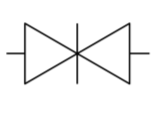
Ball Valves – used in seawater, sanitary, trim and drain, air, hydraulic, and oil transfer systems (ball inside valve to start/stop flow)

Butterfly Valve - small/quick acting; used in low pressure, low temp systems
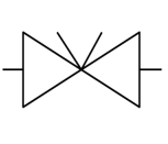
Check Valves – prevent fluid from flowing in wrong direction

Positive Displacement: CONSTANT FLOW; pumps displace a specific quantity of fluid regardless of resistance to flow
Non-Positive Displacement: VARIABLE FLOW; pumps displace a variable output of fluid depending on the resistance to flow
Naval Pipe Hangers
Rigid Hangers: Fasten piping or equipment firmly to the ship's structure with no flexibility, providing solid support where thermal expansion and vibration dampening are not required.
Spring Hangers: Use calibrated compression springs to support system weight while accommodating movement caused by thermal expansion and contraction (commonly used on high-temperature systems like steam lines).
Resilient Hangers: Dampen machinery and fluid vibrations before they can transmit through the hull into the water. (The biggest takeaway for resilient mounts is that they minimize noise.
Electrical Principles & Distribution
Requirements for Generating Electricity:
Conductor
Magnetic Field
Relative Motion
Prime Movers: Provide the mechanical rotation (relative motion) to drive shipboard generators:
Gas Turbines
Diesel Engines
Steam Turbines
Standard Power Ratings:
Standard Surface Ships: , , 3-phase AC power
Aircraft Carriers (CVNs): , , 3-phase AC power
Home Electrical Systems (Grounded):
Configuration: Neutral wire is tied directly to earth ground.
Primary Goal: Personnel safety—a single ground fault creates a short circuit that trips the breaker immediately, cutting power to prevent electrical shock.
Shipboard Electrical Systems (Ungrounded):
Configuration: The electrical distribution system is isolated and floating relative to the metal hull.
Primary Goal: Operational reliability and combat survivability.
Key Advantage: A single ground fault will not trip breakers or interrupt
NSTM 300 Electrical
Drive Train Components & Bearings
The propulsion drive train transfers mechanical torque generated by the Main Reduction Gear (MRG) directly to the propeller to propel the ship through the water.
Main Thrust Bearing: Absorbs axial thrust transmitted through the shaft and transfers it to the ship's hull structure to drive the ship forward.
Bulkhead Seal: Provides a flexible, air- and watertight seal where the propulsion shaft penetrates interior watertight bulkheads.
Line Shaft Bearing: Provides radial support to align the shaft within the ship; lubricated and cooled by lube oil.
Stern Tube Seal: Provides radial support and maintains watertight integrity where the shaft penetrates the ship's outer hull; lubricated and cooled by seawater.
Strut Bearing: Provides final external radial support to the shaft immediately forward of the propeller; lubricated and cooled by seawater.
Thrust Transmission Process
Propeller rotation develops axial thrust along the propulsion shaft.
The Main Thrust Bearing absorbs this axial load and transmits the physical force to the ship's foundation, driving the vessel forward.
Main Reduction Gear (MRG)
Core Purpose: Converts high-speed, low-torque prime mover rotation into low-speed, high-torque propeller shaft rotation.
Design Characteristics:
Dual Input: Accepts two input pinion shafts per reduction gear assembly.
Double Reduction: Two-stage gear reduction used for high-speed gas turbine and steam turbine plants (diesel-powered LSD/LPD classes use single reduction).
Double Helical: Opposed angled gear teeth eliminate axial gear thrust.
Locked Train: Balances tooth loading across gear sets to prevent gear crawling.
Articulated: Quill shafts allow gears and pinions to float independently, providing flexibility and accommodating minor shaft misalignments.
Turning Gear: Electrically driven mechanism used to slowly rotate the gear train during PMS or inspections; never engaged underway.
Fuel and Lube Oil Quality Management
Shipboard Fuel Types:
JP-5: jet fuel.
F-76: ship fuel.
Critical Properties:
Flash Point: The minimum temperature at which liquid fuel produces sufficient vapor to ignite in air.
Viscosity: A liquid's internal resistance to flow (controlled aboard ship through pre-heaters).
Testing Requirements:
Clear and Bright Test: Primary visual test to verify fuel is free of suspended water (haze) and particulate contaminants.
Testing Timeline: Fuel and lube oil must be sampled and tested when taking on fuel, when transferring from storage to service tanks, and prior to sending fuel from service tanks to the engine.
Standard Lubricant: The US Navy utilizes 2190 Lube Oil.
Steering Checks (PMS / MRC):
Conducted within prior to any evolution requiring Restricted Maneuvering Doctrine (RMD).
Test steering gear operability from all controlling stations.
Inspect hydraulic fluid levels and lubricate the rudder assembly.
Safety Precautions:
Steering Stops: Maximum rudder angle is limited to using copper and steel stops.
Helm Safety Officer: Stationed to supervise helm operation and verify proper rudder response.
Ram Steering Gear System:
Electro-hydraulic system utilizing opposed hydraulic rams and cylinders to apply mechanical force to the rudder stock.
Emergency Equipment:
Auxiliary electric pumps
Emergency hand pumps
Ratchet wrenches for manual operation
Aft Steering (Emergency Backup):
Primary backup station manned during casualties, RMD, or special evolutions.
Watch Team: Engineman (EN), Helmsman, and Safety Officer.
Steering
Steering Checks (PMS / MRC): Completed within prior to any evolution requiring Restricted Maneuvering Doctrine (RMD). Verifies gear operability across all control stations, checks hydraulic fluid levels, and lubricates the rudder assembly.
Safety Precautions:
Steering Stops: Restrict maximum rudder travel to via copper and steel mechanical stops.
Helm Safety Officer: Supervises helm watchstanders and confirms proper rudder response.
Ram Steering Gear System: Electro-hydraulic unit employing opposed hydraulic rams and cylinders to apply force to the rudder stock.
Emergency Equipment: Auxiliary electric pumps, emergency hand pumps, and manual ratchet wrenches.
Aft Steering (Emergency Backup): Manned during casualties, RMD, or special evolutions.
Watch Team: Engineman (EN), Helmsman, and Safety Officer.
Distilling Plants & Potable Water Management
Distillation Technologies:
Flash-Type Distillers: Uses low-pressure auxiliary steam under vacuum to boil and distill seawater.
Reverse Osmosis (RO): Forces pressurized seawater across semi-permeable membranes to filter out dissolved minerals and contaminants.
Water Chemical Treatment: Potable water is disinfected primarily using a brominator; chlorine hypochlorite treatment serves as an authorized backup.
Testing Responsibilities:
Medical Department: Tests shore source water prior to receipt, tests shipboard potable storage tanks daily, and samples various distribution outlets daily.
Engineering Department: Tests potable water after chemical treatment, tests tanks prior to placing them in service, and tests immediately following bromine cartridge replacements.
Compressed Air Systems
Pressure Ratings & Color Coding:
Low Pressure (LP): (piping marked tan). Normal vital and non-vital ship service headers operate at .
Medium Pressure (MP): (piping marked tan).
High Pressure (HP): (piping marked dark grey). HP air plants are rated to maintain .
Compression Types: Positive displacement and dynamic compression methods.
Applications & Protective Valves:
Major HP Users: Torpedo tubes, SCBA recharge stations, helicopter support services, VLS deluge arrays, and emergency backup for low-pressure systems.
Priority Valve: Automatically secures air to non-vital loads during high demand to ensure vital systems stay pressurized; begins throttling shut at and shuts completely at .
Shipboard Refrigeration & Cooling
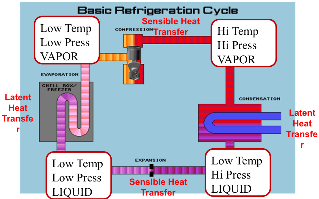
Example Question: What is the relationship between temperature and pressure? Direct Relationship (high temp = high pressure and vice versa)
Cooling Distribution Types:
Direct Systems: Circulate pressurized refrigerant directly to evaporator coils positioned inside the refrigerated compartment or air-handling unit.
Indirect Systems: Circulate refrigerant to a heat exchanger or water chiller that cools fresh water. Cooled fresh water is then circulated to cooling coils throughout ship
Propulsion Plants by USN Ship Class
Diesel Engines
Ship Classes: LPD, LSD, RHIBs, LCUs
Gas Turbines
Ship Classes: CG, DDG, LCAC
Hybrid Propulsion
Ship Classes: LCS, LHA-6, LHA-8
LCS Configuration: Gas turbines for high speeds; diesel engines for low-speed cruising
LHA Configuration: Gas turbines for high speeds; electric propulsion motors (powered by diesel generators) for low-speed cruising
Steam Plants
Ship Classes: CVN, SSN / SSBN / SSGN, LHD, LCC
Basic Steam Cycle (Rankine Cycle)
Generation: Liquid water is heated in a boiler or steam generator to produce high-pressure steam.
Expansion: High-pressure steam expands across turbine blades to generate rotational mechanical work.
Condensation: Spent low-pressure exhaust steam is cooled in a condenser, returning to liquid water.
Feed: Feed pumps pressurize and deliver the condensed water back into the steam generator.
Gas Turbine Cycle (Brayton Cycle)
Intake: Outside air is drawn into the engine via intake louvers and ducting.
Compression: Axial or centrifugal compressor blades compress and heat the incoming air.
Combustion: Fuel is injected into the combustion chamber and ignited, generating high-temperature, high-pressure gas.
Expansion: Expanding combustion gas flows across turbine wheels to drive the compressor and the output shaft.
Exhaust: Spent gases are discharged overboard through the exhaust stack.
Diesel Engine Cycle
Intake: Fresh air is drawn into the cylinder as the piston travels downward.
Compression: The piston moves upward, compressing the air to high pressure and high temperature.
Power: Fuel is injected and auto-ignites from the heat of compression, driving the piston downward.
Exhaust: The piston travels upward to force spent exhaust gases out through the open exhaust valve.