Instructions and Structures
-Group of valid instructions that a processor cam execute
Arithmetic Operations
add, subtract, multiply, divide, 2’s complement operation (multiplies by -1).
Logical Operations
AND, OR, XOR, Complement
Load/store operations (move=copy)
move data from external memory into processor or vice verse
move data within processor (between registers)
data movement within memory normally not possible
Load: memory→processor
Store: Processor→memory
Input/Output
mode data from I/O into processor or vice verse
input: I/O→processor
Output: processor→I/O
Branch
Change the order of instruction execution (jump to different program selection)
Does this by changing contents of PC
Unconditional branches/jumps
Branch always taken
Conditional Branch
Branch taken depending on condition code register flags
Stack operations
implement dynamic data storage
Can push registers onto the stack and pull them back off
Subroutine operations
implement function/procedure calls/returns
CISC - complex instruction set computer
large instruction set
high-level operations
requires microcode interpreter
RISC = reduced instruction set computer
simple, atomic instructions
small instruction set
directly executed by hardware
relies on highly complex compilers
Basic Notation
Decimal number: 10
Hex Number: $10
Binary Number: %10
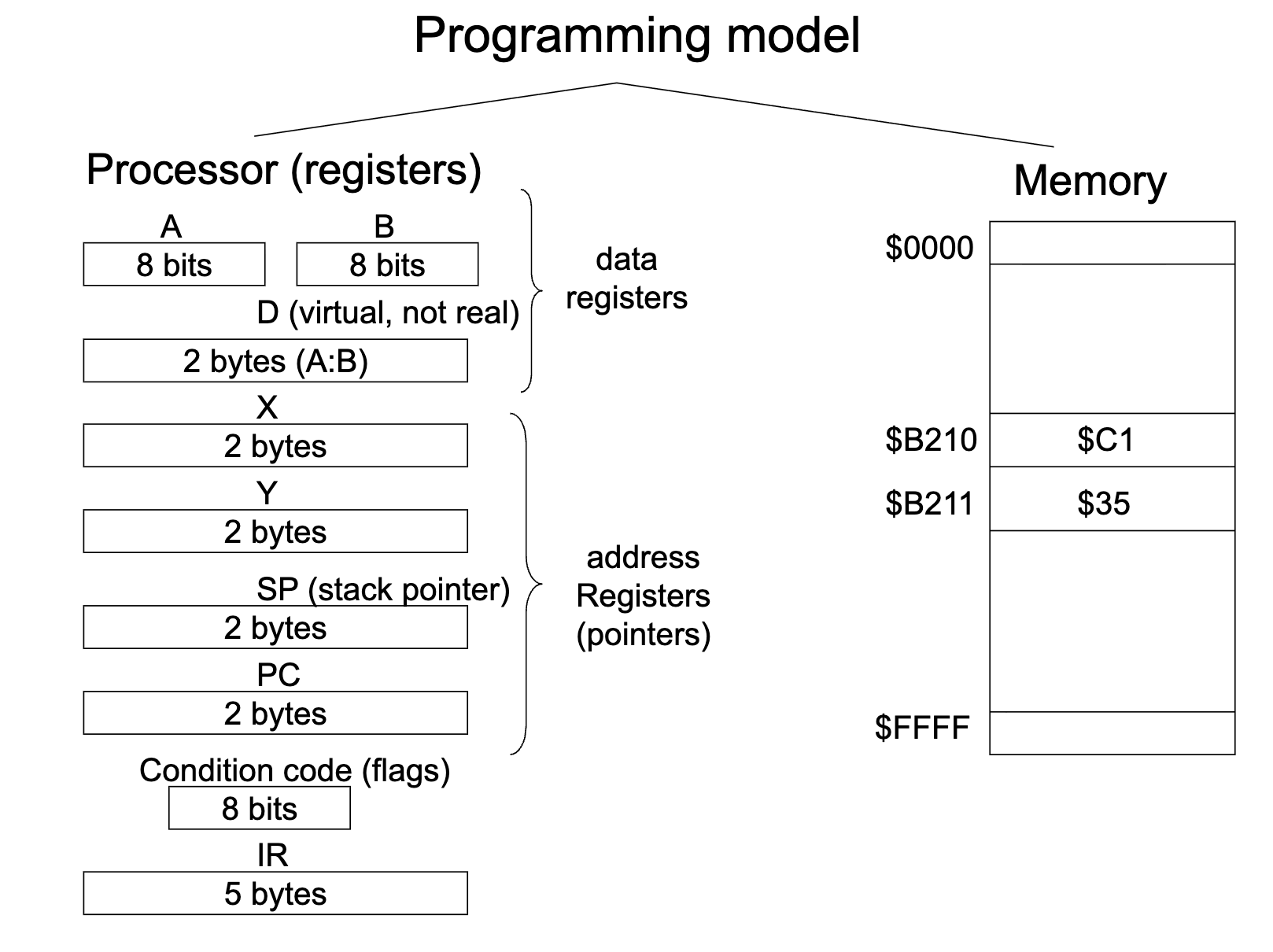
Motorala/Freescale/NXP 68HC11 Microcontroller
8-bit wide data bus
16-bit wide address bus
64K memory cells addressable
address range: $0000 - $FFFF
Divide memory into 256 byte pages: page number = MSB of address
Page 0: $0000 - $00FF
Page 1: $0100 - $01FF
Page 255: $FF00 - $FFFF
Could be AA (accumulator A) and AB (accumulator B)
D uses A and B as one combined register
PC (program counter) is a two byte counter because we store memory address’ in it (which are 16-bits)
IR (instruction register) is 5 bytes because Instructions can be 1-5 bytes, they are flexible. Instructions are stored in memory
Each memory cell can only store 1 byte. Instructions can be stored in consecutive memory cells. flip flops are used to store memory (either 0 or 1) so there is always something stored in each memory cell. RAM is volatile memory, so when you turn your power back on you will have totally random bit strings stored when you turn the power back on.
can only get 1 byte onto the data bus, so it would take 3 clock ticks to grab a 3 byte instruction.
Languages
Machine language
instructions number code (bytes in memory)
ex) $BB, $C2, $00
Assembly Language (higher than machine language, lower than C)
Instruction mnemonics (Program source code)
ex) ADDA $C200 (Add memory address $C200 into A register)
Assembler translates mnemonics into machine language
Disassembler will be on homework. Assembler WILL be on exam!!!
Running programs:
Controller is responsible for fetching and executing the instruction. Has a fetch engine and execution engine. ALU and RAM are passive
Fetch Phase: (PC) = $C200 → AB(address bus): R/W line = read memory: put M(AB)=$BB onto data bus. processor: store (DB) into IR. (PC)=(PC)+1=$C201
Controller(fetch engine) fetches the instruction into the instruction register.
Fetches the first byte of an instruction (operation code (opcode)) and stored it in the IR
Send the address, from the program counter, of the memory slot we want to grab on the address bus (the address is coming from the program counter(instructions) points to the next instruction)
Now send the read/write signal to tell the RAM if we need to write into the RAM or send something out (read).
This causes the RAM to look at the address on the address bus, select that memory cell, looks at read/write bus, if read, puts it on the data bus
Controller clocks this into the instruction register
processor decodes the instruction→ADDA, 3 bytes. (BB is a 3 byte instruction)(knows it is a 3 byte instruction because that information is stored in the fetch engine part of the controller. A fetch engine is a finite state machine, which only has flip flops. When you design a final state machine, you come up with a next state and present state and k table. The finite state machine’s ability to find the 3 bytes is hardcoded into the state transition and how you design the transitions)
Repeats the exact same procedure, fetching all bytes of the instruction
Execution phase, also a finite state machine so it knows this is a 3 byte instruction (state transition diagram of the machine): ADDA $C210: (A) + ($C210)→(A). It must add the value at $C210 to A and store it in A
Get the data item out of memory into the ALU by sending the location in the EA on the address bus.
Tell the memory to read
Wait for next memory cycle
RAM puts it on the data bus (just a copy)
The controller kicks the data bus into the ALU and sends it to the adder.
Add A and store back into A register.
Fetch/Decode/Execute architecture
Addressing Modes
Every instruction has at least 1 addressing mode
The addressing mode determines how to obtain effective address
68HC11 Addressing Modes:
Extended addressing (for variables) (3 Byte instruction)
EA = 16-bit address given in instruction (hard coded)
ADDA $C210 → $BB, $C2, $10 → EA = $C210
address range: whole memory
Direct Addressing (for variables) (2 Byte instruction)
EA = 16-bit (always 16-bit because the address bus is 16 bit); MSB = $00, LSB given in instruction
ADDA $C2 → $9B, $C2 →EA = $00C2
Address range: Page 0
Inherent Addressing (stored in ALU)
No EA to be generated; data in processor, not in memory; or data not needed
ABA → $1B : (A) + (B) → (A)
Address range: N/A
Immediate Addressing (for constants) (embedded in the executable itself and retrieved by fetch engine)
No EA to be generated; Data in instruction
ADDA #$C2 → $8B, $C2 → (A) + $C2 → (A)
Address range: N/A
Indexed Addressing (for arrays/pointers) (Indexed X or indexed Y)
EA = (X) + offset; Uses index registers X or Y as a base address instruction provides a 1-Byte unsigned offset
ADDA $C2,X → $AB, $C2; EA = (X) + $C2
Address Range: (X) → (X) + $FF (255)
Relative addressing (branches)
Change program flow; jump to different section
Change contents of PC (program counter)
Branch instruction: opcode + 1-byte signed offset
BRA 8 → $20, $08 → (PC) + 8 → (PC)
Endian Data Format
STD $C200: D→ M:M+1
Big Endian Format: stores Most Significant Byte (MSB) first ($C200), then the LSB ($C201) (Motorola)
Little Endian Format: stores LSB ($C200) first then MSB ($C201) (Intel)
Condition Code Register
N, Z, V, C flags settings depend on data item (D) stored in register or memory at end of instruction execution.
N = negative flag = d_7
Z = zero flag = d_7 +d_6 + … + d_0
V = overflow flag (signed numbers)
C = carry flag (unsigned number overflow)
LDAA #$10 0001 0000
ADDA #$F0 +1111 0000
→ 0000 0000. N=0, Z=1, C=1, V=0
LDAA #$90 1001 0000
ADDA #$90 +1001 0000
→ 0001 0000. N=0, Z=0, C=1, V=1
LDX #$9000
X=$9000. N=1, Z=0, C not touched, V=0 (always set to zero as per the pdf legend)
Branches
Branches are most often used after a comparison instruction. When the branch is taken, it changes the Program counter by adding/subtracting the offset.
BRA: Branch always, always jump to the destination of the branch
BRN: branch never, has to have this because the branches are orthogonal (comes with the opposite) (never used)
BEQ: branch if equal, if Z=1
BNE: branch if not equal, if Z=0
BMI: branch if minus, if N=1
BPL: branch if plus, if N=0
BCS: branch if carry set, if C=1
BCC: branch if carry cleared, if C=0
BVS: branch if overflow set, if V=1
BVC: branch if overflow cleared, if V=0
When dealing with unsigned numbers
BHI: branch if higher, if C+Z=0
BHS: branch if higher or same, if C=0
BLO: branch if lower, if C=1
BLS: branch if lower or same, if C+Z=1
When dealing with signed numbers:
BGT: branch if greater than, if Z + (N XOR V) = 0
BGE: branch if greater or equal, if N XOR V = 0
BLT: branch if less than, if N XOR V = 1
BLE: branch less than or equal, if Z + (N XOR V) = 1