chapter 2
Key Words in Sonography
Angle of Incidence: The angle at which the sound beam strikes a surface. A 90-degree angle is optimal to capture all echoes and determine true amplitude. Incorrect angles can cause reflection issues, leading to missed structures or grayscale inaccuracies.
Axial Views: Images showing width and depth; often referred to as transverse views. Obtained by turning the transducer 90 degrees from the sagittal plane.
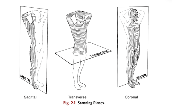
Coronal Planes: Divides the body into anterior and posterior sections. Achieved by scanning along the side of the patient or with specialized imaging techniques like transvaginal and 3D imaging.
scanning along the side of the patient, with the transducer pointing to the opposite side of the body when scanning abdominally.
Focal Zone: The area where the sound beam is narrow, improving resolution (in older transducers). Newer transducers use different technologies that do not rely on focal zones.
Long Axis: The maximum length of a structure, important for accurate measurements. Organs often lie in oblique planes, requiring careful transducer manipulation to align with the structure's orientation.
Longitudinal Views: Images showing a structure’s length and depth. Obtained when the ultrasound beam enters the body from an anterior or posterior approach, typically perpendicular to the floor.
Measurement: Accurate and reproducible measurements are critical for good patient care; needs to be correctly measured. Measurements are affected by the transducer's angle relative to the organ.
scanning planes are used to establish the direction from which the ultrasound beam enters the body and the anatomic portion of anatomy being visualized from that direction.
Oblique Orientation: Slanted or angled scanning planes, achieved by twisting/rotating the transducer. Useful for visualizing the longest length of a structure.
Orientation: The position of an organ in the body. Requires understanding anatomical relationships and variations.
Positional Orientation: Ensuring the transducer is correctly aligned with the image on the screen. Manufacturers provide marks on the transducer to ensure correct orientation.
Pressure: Applying the correct amount of pressure can help improve image quality. Communicate with the patient when and why pressure adjustments are needed.
Sagittal Planes: Divides the body into right and left sections. Can be mid-sagittal (dividing the body equally) or para-sagittal (parallel to the midline).
planes would be obtained by moving the transducer to the right or left side of patient’s body
Short Axis: The width of a structure, measured at its widest margins. Obtained by rotating 90 degrees from the long axis.
Transverse Planes: Divides the body into superior and inferior sections. Perpendicular to the sagittal plane, achieved by turning the transducer 90 degrees.
the transducer is turned 90 degress and is moved up toward the head or down toward the feet on the patient’s body.
Evaluating Sonographic Images
Plane Identification: Determine the plane used to obtain the image (e.g., supine, coronal). Crucial for proper interpretation and correlation with anatomical landmarks.
Scanning Plane Identification: Know the scanning plane (longitudinal, transverse). Impacts the visualized anatomical relationships and measurements.
Transducer as Flashlight: The transducer only visualizes what's in the sound beam's path. Understand the limitations of the technology; structures outside the beam's path will not be visible.
Normal Appearance: Understanding normal sonographic appearance is crucial for identifying pathology. Requires extensive knowledge of anatomy and variations.
Objectives of Scanning Planes and Methods
Define key words.
Explain how ultrasound uses body and scanning planes to image the body.
Differentiate between scanning planes and views.
Interpret scanning planes.
Apply scanning methods and manipulate the transducers.
Produce accurate measurements.
Identify surface landmarks.
Anatomic Planes in Sonography
Scanning planes in sonography align with anatomic body planes.
Image plane depends on transducer location and sound beam orientation.
Sagittal Planes
Mid-Sagittal Plane: Divides the body into equal right and left sections.
Often labeled as midline (ML) on images.
Para-Sagittal Planes: Parallel to midline, to the right or left.
Achieved by moving the transducer to either side of the body.
Unless noted, sagittal refers to parasagittal.
Transverse Planes
Divides the body into superior and inferior sections.
Perpendicular to the sagittal plane.
Transducer turned 90 degrees and moved up/down the body.
Coronal Planes
Divides the body into anterior and posterior sections.
Obtained by scanning along the side of the patient, transducer pointing to the opposite side during abdominal scans.
Also obtained with transvaginal and 3D imaging.
Scanning Planes Overview
Scanning planes determine the direction of the ultrasound beam entering the body.
They indicate the anatomic portion being visualized from that direction.
Often from an oblique orientation (slanted/angled).
Degree of obliquity depends on the structure’s orientation in the body.
Oblique scanning often visualizes the longest length of a structure.
Body structures viewed in longitudinal and axial planes.
Longitudinal views show length and depth.
Axial views show width and depth (often termed transverse).
Sagittal and longitudinal terms used interchangeably (e.g., Long Aorta).
Ultrasound Scanning Planes
Sagittal Scanning
Ultrasound beam enters the body from anterior (supine) or posterior (prone) approach.
Transducer usually perpendicular to the floor.
Evaluates structures in:
Anterior direction.
Posterior direction.
Superior direction.
Inferior direction.
NOTE: Medial and lateral aspects not seen on sagittal scans. Move transducer to parasagittal planes to visualize adjacent anatomy.
Transverse Scanning
90 degrees to the sagittal plane.
Beam enters from anterior or posterior direction.
Sound beam perpendicular to the floor or slightly angled.
Evaluates structures in:
Anterior direction.
Posterior direction.
Medial direction.
Lateral direction.
NOTE: Superior and inferior aspects are not seen on a transverse scan. Move the transducer superiorly or inferiorly to visualize adjacent anatomy.
Coronal Scanning Plane
Ultrasound beam enters from right or left lateral direction.
Transducer placed along the side of the patient’s body.
Both longitudinal and transverse images can be obtained in this plane.
Used to scan under bowel or between ribs.
Most liver images are variations of a coronal plane to see more liver parenchyma.
Scanning Planes and Anatomy Visualization
Longitudinal/Long Axis Approach:
Anterior aspect.
Posterior aspect.
Superior aspect.
Inferior aspect.
Transverse Approach:
Medial aspect.
Lateral aspect.
Superior aspect.
Inferior aspect.
Scanning Skills and Techniques
Primary Role: Provide interpretable images for diagnosis.
Requires practice, good scanning methods, image optimization, critical thinking, and anatomical/pathological knowledge.
Transducers
Advances in transducer design offer better penetration, resolution, and Doppler sensitivity.
Ergonomic designs protect sonographer’s joints.
Shapes determine the field of view.
Frequency (MHz) determines penetration depth and resolution.
Low-frequency transducers:
Most penetration.
Less resolution.
High-frequency transducers:
Less penetration.
Better resolution, used for superficial structures.
Transducer types and frequencies:
Curved linear array:
Abdominal, obstetric, gynecologic imaging.
Frequencies: 2-10 MHz.
Example: C5-2 (curved, 2-5 MHz range).
Vector/sector array:
Low frequency for scanning between ribs, pediatrics.
Examples: V4-1 (low frequency), S12-4 (newborn/infant).
Linear array:
Largest tissue amount displayed.
Superficial structures: thyroid, breast, scrotum.
Doppler exams: carotid, lower extremity vessels.
Examples: L12-5 (carotid), L18-5 (thyroid).
Transvaginal/Transrectal:
Small scanning head on a long shaft.
Better resolution of pelvic organs or prostate.
Examples: C9-3 (endovaginal), C12-5 (prostate), EV9-3 (endovaginal).
Hockey stick:
Small size for intraoperative imaging and musculoskeletal studies.
Example: L12-5 (carotid endarterectomy).
Three-dimensional imaging (3D):
Obstetrics, gynecology, liver masses, thyroid, arterial disease.
Designated as 3D transducer (e.g., 3D9-3).
Newer models are all electronic with no moving parts.
Focal Zone (older transducers):
Sound beam is narrow to improve resolution.
Indicated by a mark on the image; area of interest should be positioned in this zone.
Newer transducer technologies don’t use focal zones.
Scanning Techniques
Transducer held in various ways (e.g., like a pencil).
Fluid motions combining angling, rotating, and moving the transducer.
Angle of incidence: Angle at which the sound beam strikes the structure’s surface.
90-degree angle ensures all echoes are received, and true amplitude is determined.
Incorrect angles cause some echoes to reflect away, resulting in missing structures or incorrect grayscale.
Applying correct pressure improves images; tell the patient when and why you need to apply pressure.
Positional orientation needed to align the transducer with the image on the screen.
Manufacturers provide marks on the transducer to ensure correct orientation.
If the image appears reversed, rotate the transducer 180 degrees.
Accurate Measurements
Critical for good patient care, especially in follow-up exams.
Organs often lie in an oblique plane; scan according to the structure’s orientation.
Long axis: Maximum length of a structure.
Pancreas: Lies obliquely, long axis seen in a transverse oblique plane. Rotate the transducer counterclockwise to visualize the entire length.
Kidney: Lies obliquely; sagittal plane must be oblique to match the kidney’s angle. Rotate the transducer clockwise to see the entire length.
Gallbladder: Long axis is variable, seen in any plane. Rotate transducer to view the long axis.
Short axis: Rotate 90 degrees from the long axis for width measurements at the widest margins.
Tilt the transducer to be perpendicular to the organ; otherwise, measurements will be inaccurate.
Accurate measurements affect patient care and skills as a sonographer.
Transducer Positions and Motions
Perpendicular: Transducer straight up and down.
Sliding: Fluid motion, slowly slide the transducer along