Transport Layer Notes
TCP Connection Establishment
The process involves a three-way handshake:
SYN (synchronize)
The client sends a SYN packet (SYN=1) to initiate the connection.
It includes the initial sequence number (seqnum=x) the client will use.
SYN-ACK (synchronize-acknowledge)
The server responds with a SYN-ACK packet (SYN=1) to acknowledge the client's request.
It includes its own initial sequence number (seqnum=y).
It also acknowledges the client's sequence number (ACK=1, ACKNUM=x+1).
ACK (acknowledge)
The client sends an ACK packet (ACK=1, ACKNUM=y+1) to acknowledge the server's starting sequence number.
Data transfer can begin after this step.
Diagram:
SYNbit=1, Seq=x
SYNbit=1, Seq=y, ACKbit=1; ACKnum=x+1
ACKbit=1, ACKnum=y+1
Connection Establishment: Packet Loss
SYN Loss:
The client waits for a SYN-ACK message.
A timeout occurs.
The client re-sends the SYN message.
SYN-ACK Loss:
Handled the same way as SYN loss.
ACK Loss:
This is problematic.
The server keeps the connection in a "half-open" state, awaiting a potential client ACK.
This can be exploited in a Denial-of-Service (DOS) attack.
Servers use "SYN Cookies" to mitigate the impact of many half-open connections.
TCP Connection Closing
The process involves a four-way handshake:
Client FIN:
The client sends a FIN packet (FIN=1) to indicate it is done sending data.
Server ACK:
The server acknowledges the FIN (ACK=1).
The server may continue sending data.
Server FIN:
The server sends a FIN packet (FIN=1) to indicate it is done sending data.
Client ACK:
The client acknowledges the server's FIN (ACK=1).
Diagram:
Client FIN: FINbit=1, ACKbit=1, seq=x, ack=y
Server ACK: FINbit=0, ACKbit=1, seq=y, ack=x+1
Server FIN: FINbit=1, ACKbit=1, seq=y, ack=x+1
Client ACK: FINbit=0, ACKbit=1, seq=x+1, ack=y+1
Connection Closing: Packet Loss
Client FIN Lost:
The server doesn't know the client wants to close.
A timeout occurs.
The client re-sends the FIN.
Server ACK Lost:
Handled the same way as client FIN lost.
The server recognizes the duplicate FIN and resends the ACK.
Server FIN Lost:
Handled the same way as client FIN lost.
Client ACK Lost:
This is problematic.
The server waits for a long timeout (120+ seconds).
It does not reassign the port or reuse the connection to avoid issues with potential duplicate ACKs in the next connection.
TCP State Machine (FSM) for Opening/Closing
States:
CLOSED
LISTEN
SYN RECEIVED
SYN SENT
ESTABLISHED
FIN WAIT 1
FIN WAIT 2
CLOSING
TIMEOUT
CLOSE WAIT
LAST ACK
The state machine illustrates the transitions between these states during connection establishment and termination, including handling timeouts and packet loss.
Congestion
Informal Definition: Too many sources sending too much data too fast for the network to handle.
Manifestations:
Long delays (queueing in router buffers).
Packet loss (buffer overflow at routers).
Difference from Flow Control:
Congestion Control: Too many senders sending too fast.
Flow Control: One sender sending too fast for one receiver.
Congestion is a top-10 networking problem.
Throughput and Capacity
Throughput cannot exceed available capacity.
Scenario: Hosts A and B sharing a link to Router Y with capacity R.
If A and B both send data at rate R, they must share the bandwidth to Y.
If the bandwidth from Router X to Router Y is shared fairly, Hosts C and D will each receive at most bps.
Best Case: Throughput at which data is received by the application in Host C is bps.
Let:
= Rate at which host A sends data out.
= Rate at which new data is received by the application.
Best Case Scenario: As increases, increases up to R/2
Equation:
Throughput can never exceed available capacity.
Ideal Cases
Ideal Case 1: Infinite Buffers
The buffer at Router X has infinite capacity.
No packets are dropped; they may take longer to arrive.
No packet drops ⇒ all the bits per second getting to Host C have been sent exactly once.
Ideal Case 2: Finite Buffers but Perfect Knowledge of Capacity
Host A has perfect knowledge of the available buffer capacity.
Host A only sends when router buffers are available.
No packet drops ⇒ all the bits per second getting to Host C have been sent exactly once.
Packet Loss
In reality, Host A may not have real-time information about available buffer capacity.
With reliable data transfer, if a packet is lost, the transport layer will retransmit the corresponding data segments.
Retransmission = Wasted capacity.
Costs of Congestion
More work (retransmission) for given receiver throughput.
Unneeded retransmissions: the link carries multiple copies of a packet, decreasing maximum achievable throughput.
Congestion Collapse
Realistic Scenario: Retransmissions triggered by loss throughout the network.
Whenever a packet is dropped at Router Y, the work done by Router X (buffering and forwarding) is wasted.
Upstream transmission capacity / buffering wasted for packets lost downstream.
In extreme cases, leads to congestion collapse, where the network keeps carrying retransmitted packets only to be dropped later.
No data gets delivered. (This happened in the early days of the Internet!)
Avoiding Congestion
Throughput can’t exceed available capacity.
Sending over capacity ⇨ packet loss or long delays.
Packet loss or long delay ⇨ retransmission.
Retransmission ⇨ Wasted capacity.
Constant retransmission throughout the network ⇨ congestion collapse.
Congestion Control: Have each sender estimate the available capacity in the network before sending, and only send out what the network can handle.
Insights on Congestion
Delay increases as capacity is approached.
Unneeded duplicates further decrease effective throughput.
Loss/retransmission decreases effective throughput.
Throughput can never exceed capacity.
Approaches to Congestion Control
End-to-End Congestion Control:
No explicit feedback from the network.
Congestion inferred from observed loss and delay.
Approach taken by TCP.
Network-Assisted Congestion Control:
Routers provide direct feedback to sending/receiving hosts with flows passing through the congested router.
May indicate congestion level or explicitly set sending rate.
TCP ECN, ATM, DECbit protocols.
TCP Congestion Control: AIMD (Additive Increase/Multiplicative Decrease)
Senders can increase the sending rate until packet loss (congestion) occurs, then decrease the sending rate on a loss event.
Sawtooth Behavior:
Additive Increase: Increase sending rate by 1 maximum segment size (MSS) every Round Trip Time (RTT) until loss is detected.
Multiplicative Decrease: Cut sending rate in half at each loss event.
Multiplicative Decrease Detail:
Cut in half on loss detected by triple duplicate ACK (TCP Reno).
Cut to 1 MSS when loss is detected by timeout (TCP Tahoe).
Why AIMD?
A distributed, asynchronous algorithm shown to:
Optimize congested flow rates network-wide.
Have desirable stability properties.
TCP Congestion Control Details
TCP sender limits transmission based on the congestion window (cwnd).
Equation:
LastByteSent - LastByteAcked <= cwnd
TCP sending behavior:
Send roughly cwnd bytes, wait RTT for ACKs, then send more bytes.
TCP Rate Approximation:
TCP Slow Start
When a connection begins, increase rate exponentially until the first loss event:
Initially, cwnd = 1 MSS.
Double cwnd every RTT.
Summary: Initial rate is slow but ramps up exponentially fast.
TCP: From Slow Start to Congestion Avoidance
Question: When should the exponential increase switch to linear?
Answer: When cwnd gets to 1/2 of its value before the timeout.
Implementation:
Variable ssthresh (slow start threshold).
On a loss event, ssthresh is set to 1/2 of cwnd just before the loss event.
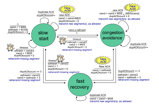
TCP Congestion Control Algorithm Summary
Slow Start:
New ACK:
If cwnd < ssthresh, cwnd grows exponentially.
If cwnd ≥ ssthresh, go to congestion avoidance.
Three Duplicate ACKs:
Set ssthresh ← cwnd/2
Set cwnd ← ssthresh
Go to congestion avoidance.
Timeout:
Set ssthresh ← cwnd/2
Set cwnd ← 1
Go to slow start.
Congestion Avoidance:
New ACK:
cwnd increases linearly (cwnd = cwnd + MSS*(MSS/cwnd)).
Three Duplicate ACKs:
Set ssthresh ← cwnd/2
Set cwnd ← ssthresh
Timeout:
Set ssthresh ← cwnd/2
Set cwnd ← 1
Go to slow start.
TCP CUBIC
An alternative to AIMD to probe for usable bandwidth.
Insight:
: Sending rate at which congestion loss was detected.
The congestion state of the bottleneck link probably hasn’t changed much.
After cutting rate/window in half on loss, initially ramp to faster, but then approach more slowly.
: point in time when TCP window size will reach
itself is tunable
Larger increases when further away from
Smaller increases (cautious) when nearer
Increase as a function of the cube of the distance between current time and .
TCP CUBIC default in Linux, most popular TCP for popular Web servers
TCP and the Congested Bottleneck Link
TCP (classic, CUBIC) increases TCP’s sending rate until packet loss occurs at some router’s output: the bottleneck link.
Understanding congestion: useful to focus on congested bottleneck link
Insight: increasing TCP sending rate will not increase end-end throughout with congested bottleneck
Insight: increasing TCP sending rate will increase measured RTT
Goal: “keep the end-end pipe just full, but not fuller.”
Delay-Based TCP Congestion Control
Keeping sender-to-receiver pipe “just full enough, but no fuller”:
Keep bottleneck link busy transmitting but avoid high delays/buffering
Delay-based approach:
-minimum observed RTT (uncongested path)
uncongested throughput with congestion window cwnd is if measured throughput “very close” to uncongested throughput
increase cwnd linearly /* since path not congested / else if measured throughput “far below” uncongested throughput decrease cwnd linearly / since path is congested */
measured throughput = # bytes sent in last RTT interval
Congestion control without inducing/forcing loss
Maximizing throughout (“keeping the just pipe full… ”) while keeping delay low (“…but not fuller”)
A number of deployed TCPs take a delay-based approach.
BBR deployed on Google’s (internal) backbone network
Explicit Congestion Notification (ECN)
TCP deployments often implement network-assisted congestion control:
Two bits in IP header (ToS field) marked by network router to indicate congestion.
Policy to determine marking chosen by network operator.
Congestion indication carried to destination.
Destination sets ECE bit on ACK segment to notify sender of congestion.
TCP Fairness
Fairness goal: if K TCP sessions share the same bottleneck link of bandwidth R, each should have an average rate of R/K.
Is TCP Fair?
Example: two competing TCP sessions.
Additive increase gives a slope of 1 as throughput increases.
Multiplicative decrease decreases throughput proportionally.
Answer: Yes, under idealized assumptions:
same RTT
fixed number of sessions
only in congestion avoidance
Fairness Considerations
Fairness and UDP:
Multimedia apps often do not use TCP because they do not want rate throttling by congestion control.
Instead, they use UDP to send audio/video at a constant rate, tolerating packet loss.
Fairness, parallel TCP connections:
application can open multiple parallel connections between two hosts
Evolving Transport-Layer Functionality
TCP, UDP: principal transport protocols for 40 years.
Different “flavors” of TCP developed for specific scenarios.
Moving transport–layer functions to the application layer on top of UDP (e.g., HTTP/3: QUIC).
QUIC:
application-layer protocol, on top of UDP increase performance of HTTP
QUIC: Connection establishment
1 handshake reliability, congestion control, authentication, encryption, state established in one RTT
QUIC: Streams
multiple application-level “streams” multiplexed over single QUIC connection