Module 4
HELICOPTER
It is an aircraft that uses rotating wings to provide lift, propulsion, and control. They are classified as rotorcraft aircraft or rotary-wing to distinguish them from fixed-wing aircraft because the helicopter derives its source of lift from the rotor blades rotating around a mast.
An aircraft that is lifted and propelled by one or more horizontal rotors, each rotor consisting of two or more rotor blades.
The word "helicopter" is adapted from the French hélicoptère, coined by Gustave de Ponton d'Amécourt in 1861.
It is linked to the Greek words: helix/helikos ("spiral" or "turning") and pteron (“wing”)
HELICOPTER OPERATION
OPERATION ON VERTICAL FLIGHT
OPERATION WITH NO VELOCITY
FORWARD FLIGHT
OPERATION AFTER LOSS OF POWER
6 FUNDAMENTAL PROBLEMS
Understanding the basic aerodynamics of vertical flight.
The lack of a suitable powerplant (engine).
Minimizing structural weight and engine weight.
Counteracting rotor torque reaction.
Providing stability and properly controlling the machine.
Conquering the problem of high vibrations
HISTORY AND DEVELOPMENT OF HELICOPTERS
Year 400 C.E. There are historical references to a Chinese kite that used a rotary wing as a source of lift.
15th Century. Leonardo da Vinci made drawings of a helicopter that used a spiral airscrew to obtain lift.
July 1754. Mikhail V. Lomonosov (Father of Russian Science) demonstrated a spring- powered model to the Russian academy of sciences.
1784. Christian de Launoy and Bienvenu demonstrated a spring-powered model to the French Academy of Sciences. It had two contra-rotating rotors of four turkey flight feathers blades each powered by a flexed bow.
1843. The first scientific exposition of the principles that ultimately led to the successful helicopter from Sir George Cayley, who is also regarded by many as the father of fixed-wing flight.
1863. Gustave de Ponton d'Amécourt built a small steam-driven model though they never achieved flight. He coined the term "helicopter" from the Greek words "helix" (spiral) and "pteron" (wing).
On September 29, 1907, the Breguet brothers, Louis and Jacques, under the guidance of the physiologist and aviation pioneer Charles Richet made a short flight in their Gyroplane No. 1, powered by a 45-horsepower engine. The Gyroplane had a spiderweb-like frame and four sets of rotors. The piloted aircraft lifted from the ground to a height of about two feet, but it was tethered and not under any control.
In November 1907, Paul Cornu, who was a bicycle maker like the Wright brothers, attained a free flight of about 20 seconds' duration, reaching a height of one foot in a twin-rotor. During this time in the United States, Igor Sikorsky is already making experiments about vertical flight, however, most of his experiments are unsuccessful.
On January 9, 1923, Juan de la Cierva made the first successful flight of an autogiro (autogyro). An autogiro operates on a different principle than a helicopter. Its rotor is not powered but obtains lift by its mechanical rotation as the autogiro moves forward through the air. It has the advantage of a relatively short takeoff and a near vertical descent, and the subsequent success of Cierva's autogiros and those of his competitors seemed to cast a pall on the future of helicopter development.
In 1936, Heinrich Focke in Germany Germany stepped to the forefront of helicopter development with the Focke Achgelis Fa 61, which had two three- bladed rotors mounted on outriggers and powered by a 160-horsepower radial engine. The Fa 61 had controllable cyclic pitch and set numerous records, including, in 1938, an altitude flight of 11,243 feet and a cross-country flight of 143 miles. • First successful helicopter
On September 14, 1939, the VS-300, the world's first practical helicopter, took flight at Stratford, Connecticut. Designed by Igor Sikorsky and built by the Vought-Sikorsky Aircraft Division of the United Aircraft Corporation, the helicopter was this first to incorporate a single main rotor and tail rotor design.
1942. Sikorsky's R-4 became the first mass- produced helicopter and was used by the U.S. military during World War II reconnaissance, search and search and rescue, medical evacuation.
1943. The Model 30/Bell 30 is the prototype for the first commercial helicopter, and the first helicopter built by Lawrence Bell (Bell Helicopter Company in the United States) with a two-bladed teetering main rotor and a tail rotor, using the gyro stabilizer bar developed by Arthur Young. It was developed into the Bell 47 of 1945, which became the first helicopter certified for civilian use in the United States (March 1946). Produced in several countries, the Bell 47 was the most popular helicopter model for nearly 30 years.
January 15, 1947. Charles Kaman developed the servo-tab control method of rotor pitch control, in which the rotor blade is twisted rather than rotated about a pitch bearing at the root. Kaman also а helicopter of the developed synchropter configuration.
On December 11, 1951, he modified his K-225 helicopter with a new kind of engine, the turboshaft engine making it the first turbine-powered helicopter in the world.
In 1954, Kaman also developed the first twin-engine turbine powered helicopter, an HTK-1 synchropter with two Boeing engines (total 350 shp) replacing a single 240 hp piston engine of the same weight in the same position.
HELICOPTER COMPONENTS
Main Rotor System
Fuselage
Empennage/Tail Boom
Stabilizers
Tail Rotor System
Airframe
Landing Gear
Transmission
Powerplant
HELICOPTER CONFIGURATIONS
Single Main Rotor + Tail Rotor
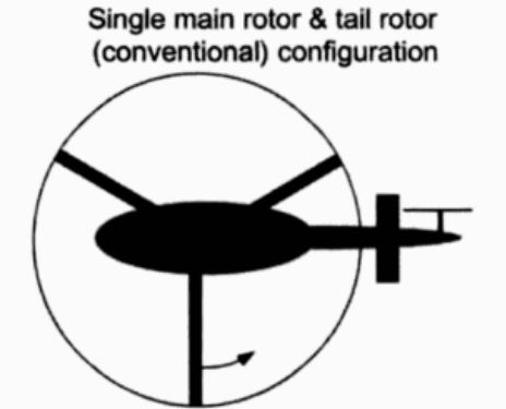
With a single main rotor helicopter, the creation of torque as the engine turns the rotor creates a torque effect that causes the body of the helicopter to turn in the opposite direction of the rotor.
To eliminate this effect, some sort of anti- torque control must be used with a sufficient margin of power available to allow the helicopter to maintain its heading and provide yaw control.
Tail Rotor System: Tail rotor, ducted fan, NOTAR
Tandem Rotor
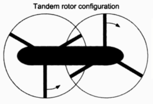
Tandem rotor (sometimes referred to as dual rotor) helicopters have two large horizontal rotor assemblies, a twin rotor system.
Tandem rotor helicopters use counter-rotating rotors, with each canceling out the other's torque.
Counter-rotating rotor blades won't collide with and destroy each other if they flex into the other rotor's pathway.
This configuration also has the advantage of being able to hold more weight with shorter blades, since there are two sets.
Coaxial Rotor
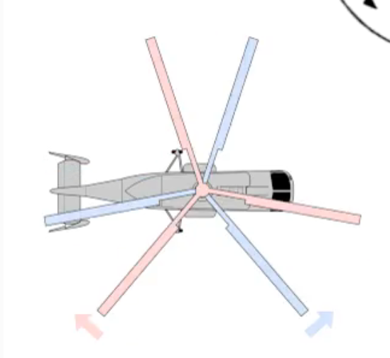
Coaxial rotors are a pair of rotors turning in opposite directions, but mounted on a mast, with the same axis of rotation, one above the other.
This configuration is a noted feature of helicopters produced by the Russian Kamov helicopter design bureau.
Intermesh Rotor
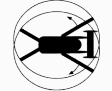
Intermeshing rotors on a helicopter are a set of two rotors turning in opposite directions, with each rotor mast mounted on the helicopter with a slight angle to the other so that the blades intermesh without colliding.
The arrangement allows the helicopter to function without the need for a tail rotor. This configuration is sometimes referred to as a synchropter.
Transverse/ Tilt Rotor
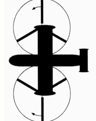
Transverse rotors are mounted on the end of wings or outriggers perpendicular to the body of the aircraft.
Like tandem rotors and intermeshing rotors, the transverse rotor also uses differential collective pitch. But like the intermeshing rotors, the transverse rotors use the concept for changes in the roll attitude of the rotorcraft.
HELICOPTER CONTROLS
Collective Pitch Control
The collective pitch control, or collective, is located on the left side of the pilot's seat with a pilot-selected variable friction control to control to prevent inadvertent movement.
The collective controls the main rotor lift by changing the pitch angle of the main rotor blades collectively (i.e., all at the same time) and independently of their positions.
Climb: Pulling the lever up increases the pitch angle of all main rotor blades, resulting in an increase in lift.
Descent: Pushing the lever down decreases the pitch angle of all main rotor blades, resulting in a decrease in lift.
Cyclic Pitch Control
The cyclic control allows the pilot to fly the helicopter in any direction of travel: forward, rearward, left, and right.
Pitch Control: Moving the cyclic stick forward or rearward tilts the main rotor disk forward or rearward, to control the helicopter about the pitch axis.
Roll Control: Moving the cyclic stick to the left or to the right tilts the main rotor disk to the left or to the right, to control the helicopter about the roll axis.
Throttle Control
Its function is to regulate engine rpm:
Twisting the throttle to the left - Increases rpm
Twisting the throttle to the right - Decreases rpm
A governor is a sensing device that senses rotor and engine rpm and makes the necessary adjustments in order to keep rotor rpm constant.
A correlator is a mechanical connection between the collective lever and the engine throttle. This system maintains rpm close to the desired value, but still requires adjustment of the throttle for fine tuning.
Antitorque Pedals
Right action: Pushing the right pedal increases tail rotor thrust and hence the helicopter turns to the right
Left action: Pushing the left pedal decreases the thrust hence the helicopter turns to the left.
MAIN ROTOR SYSTEM
The main rotor is the rotating part that provides the lift of the helicopter and powers its forward flight. The rotor consists of a mast, hub, and rotor blades.
MAST - a hollow cylindrical metal shaft which extends upwards from and is driven and sometimes supported by the transmission.
HUB - the attachment points for the rotor blades at the top of the mast.
ROTOR BLADES - rotating airfoils to create a lift for the helicopter.
Classification of Main Rotor Systems
Fully Articulated
Lead / Lag - move back and forth in plane
Flap - move up and down about an inboard mounted hinge independent of the other blades
Feather - rotate about the pitch axis to change lift
Semirigid
Tilt/ Flap
Feather
Two blades forming a continuous structure are attached to the rotor shaft with a single flap hinge in a teetering or seesaw arrangement.
As one blade flaps up, the other flaps down, using a teetering hinge.
The rotor has no lag hinges.
Similarly, a gimballed rotor has three or more blades attached to the hub without hinges, and the hub is attached to the rotor shaft by a gimbal or universal joint arrangement.
Rigid
Feather
The blades are attached to the hub without flap or lag hinges, although often with a feathering bearing or hinge.
The blade is attached to the hub with cantilever root restraint so that blade motion occurs through bending at the root.
However, the limit of a truly rigid blade, which is so stiff that there is no significant motion, is applicable only to high disk loading rotors.
Main Rotor Mast Components
Rotor shaft
Swashplates
The purpose of the swash plate is to convert stationary control inputs from the pilot into rotating inputs which can be connected to the rotor blades or control surfaces.
It consists of two main parts:
Stationary swash plate is mounted around the main rotor mast and connected to the cyclic and collective controls by a series of pushrods. It is restrained from rotating by an antidrive link but can tilt in all directions and move vertically.
Rotating swash plate is mounted to the stationary swash plate by means of a uniball sleeve. It is connected to the mast by drive links and must rotate in constant relationship with the main rotor mast.
Casing assembly
Suspension Bars
Free Wheeling Unit
The freewheeling unit automatically disengages the engine from the main rotor when engine revolutions per minute (rpm) is less than main rotor rpm.
This allows the main rotor and tail rotor to continue turning at normal inflight speeds.
The most common freewheeling unit assembly consists of a one-way sprag clutch located between the engine and main rotor transmission.
Rotor Droop
Rotor droop refers to the phenomenon where helicopter rotor blades sag or droop when the helicopter is on the ground and the rotors are not spinning at full speed. This happens because the blades are long and flexible, and without the centrifugal force generated by spinning, they bend under their own weight
Droop Stops used to prevent the blades from drooping too much and potentially hitting the helicopter's fuselage. These are mechanical devices that limit how far the blades can sag.