Week 1 - L2 Pulse-Echo Principle
Key Points
Understand the pulse‑echo principle and distance calculation.
Learn how different transducer shapes affect imaging.
Differentiate B-mode, M-mode, and 3D/Volume imaging.
Grasp Doppler fundamentals and types (PW, CW, Power).
🔊 The Pulse-Echo Principle
Core Concept
Pulse-echo technique: A method where ultrasound pulses are transmitted into the body, interact with tissues and interfaces, and return as echoes to create diagnostic images.
The pulse-echo principle is fundamentally equivalent to echolocation — the same biological mechanism used by bats and dolphins to navigate and locate objects.
🎯 Echolocation Fundamentals
Echolocation relies on three critical factors:
Factor | Description |
|---|---|
Speed of sound | Constant propagation velocity through tissue |
Time of travel | Duration for sound to return to transducer |
Direction of sound | Beam orientation and path |
Distance Calculation
The distance to a tissue interface is calculated based on the round-trip time of the echo:
Where:
= velocity of sound
= distance to interface
= round-trip time
📡 Transducers and Scan Formats
Transducer Components
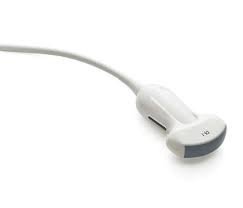
The transducer (or probe) serves as both transmitter and receiver of ultrasound pulses. The image above shows a typical handheld ultrasound transducer with cable connection.
Scan Lines and Image Quality
Scan lines form the foundation of sonographic images
More scan lines = better image quality
Real-time imaging requires many frames per second for smooth visualization
Basic Transducer Formats
Format | Shape | Typical Applications |
|---|---|---|
Linear | Rectangular | Thyroid, superficial structures |
Curved linear (convex) | Sector with curved top | Liver, abdominal organs |
Sector | Pie-shaped | Cardiac imaging (through ribs) |

The fan-shaped pattern illustrates how ultrasound beams diverge from the transducer face, creating the near field (Fresnel zone) closest to the transducer and the far field (Fraunhofer zone) where beams spread.
🖼 Modes of Imaging
B-Mode (Brightness Mode)
B-mode ultrasound: The standard grayscale imaging mode where echo amplitude determines pixel brightness.
Creates 2D anatomical images
Brightest echoes typically come from strong reflectors like bone, diaphragm, or organ boundaries
pulses are made up of 3-5
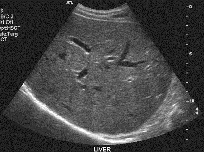
A typical B-mode ultrasound showing liver anatomy with visible internal structures and the bright diaphragm interface.
M-Mode (Motion Mode)
M-mode ultrasound: Uses a single beam path to display motion of structures over time.
Particularly useful for cardiac imaging (adult and fetal heart)
Displays structure position on the vertical axis versus time on the horizontal axis
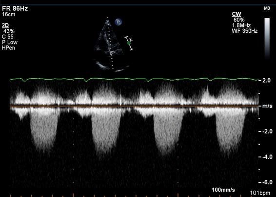
An echocardiogram demonstrating M-mode application: the top shows the 2D cardiac view with the M-mode cursor line, while the bottom displays the resulting motion tracing over time.
A-Mode (Amplitude Mode)
A-mode: The original ultrasound display where echo amplitudes are plotted as spikes, with height representing echo strength.
Primarily of historical interest
Still used in ophthalmology for precise axial length measurements
3D/Volume Imaging
Reconstructs three-dimensional datasets from multiple 2D planes
Enables surface rendering and multiplanar reconstruction
Particularly valuable in obstetrics and cardiac imaging
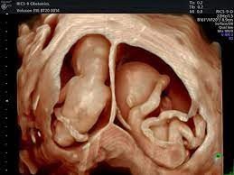
A 3D volume-rendered ultrasound image showing twins in utero, demonstrating the surface reconstruction capability of modern volume imaging.
🌊 Doppler Ultrasound
Fundamental Principle
Doppler ultrasound exploits the Doppler effect — the change in frequency of sound waves reflected from moving objects (blood cells).
Types of Doppler Ultrasound
Type | Description | Key Characteristics |
|---|---|---|
Pulsed Wave (PW) Doppler | Intermittent pulse transmission with listening periods | Range resolution; velocity limited by Nyquist |
Continuous Wave (CW) Doppler | Simultaneous transmission and reception | No velocity limit; no depth discrimination |
Pulsed Wave Doppler — Three Subtypes
1. PW Spectral Doppler
Spectral Doppler: Displays velocity waveforms showing flow direction and characteristics over time.
Demonstrates spectral waveforms with frequency/velocity on vertical axis, time on horizontal
Shows direction of flow (above/below baseline)
Distinguishes arterial (pulsatile) from venous (continuous) waveforms
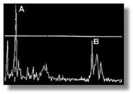
A spectral Doppler waveform showing two distinct peaks (A and B), representing different flow velocities or cardiac cycle phases. The vertical axis represents velocity/frequency, horizontal axis represents time.
2. PW Color Doppler
Color Doppler: Superimposes color-coded flow information on B-mode images.
Red and blue displays indicate direction and velocity of blood flow
Typically: red = flow toward transducer, blue = flow away
Color brightness/saturation indicates velocity magnitude
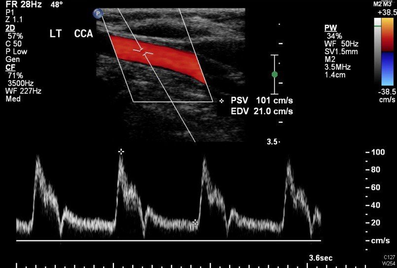
A color Doppler ultrasound of the left common carotid artery showing red coloration indicating blood flow toward the transducer, with the spectral waveform displayed below for quantitative analysis.
3. PW Power Doppler (Color Power Doppler/CPD)
Power Doppler: Displays amplitude of Doppler signal rather than frequency shift.
Based on amplitude/strength of blood cell motion, not velocity or direction
Image is superimposed over 2D B-mode
Does NOT provide directional information
Highly sensitive to slow flow states
Less dependent on angle of insonation than color Doppler
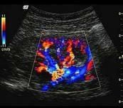
An ultrasound demonstrating color Doppler application with mixed red, blue, and yellow colors indicating complex flow patterns within a blood vessel, with the region of interest marked by a white box.
Continuous Wave (CW) Doppler
Separate transmitter and receiver crystals (or elements)
Continuous transmission and continuous reception
No upper velocity limit (not limited by Nyquist frequency)
No depth discrimination — cannot determine where along the beam flow is occurring
Requires anatomical guidance from B-mode image
Pedof transducer: A specialized CW Doppler probe without imaging capability — used when only velocity information is needed.
📊 Summary Table: Imaging Modes Comparison
Mode | Display Type | Primary Information | Key Applications |
|---|---|---|---|
A-mode | Amplitude spikes | Echo strength | Ophthalmology (axial length) |
B-mode | 2D grayscale image | Anatomy, tissue structure | General diagnostic imaging |
M-mode | Motion over time | Movement of structures | Cardiac valve motion, fetal heart |
3D/Volume | 3D reconstruction | Surface anatomy, volume | Obstetrics, cardiac chambers |
Spectral Doppler | Velocity waveform | Flow velocity, resistance | Vascular assessment, cardiac output |
Color Doppler | Color overlay on B-mode | Flow direction, velocity | Regional flow assessment |
Power Doppler | Color overlay (amplitude) | Flow presence, slow flow | Low-velocity flow detection |
🔑 Key Takeaways
The pulse-echo principle is the foundation of all diagnostic ultrasound, using the speed of sound and round-trip time to calculate distances and create images.
Echolocation requires knowledge of sound velocity, travel time, and direction to accurately locate structures in the body.
B-mode remains the standard for anatomical imaging, while Doppler techniques (spectral, color, and power) provide essential hemodynamic information.
Pulsed Wave Doppler offers range resolution but has velocity limitations; Continuous Wave Doppler measures any velocity but cannot determine depth.