CH 03 : Logic Gates And Logic Circuits
Logic Gates
==Logic Gates==: They take binary inputs and give binary outputs in an electronic circuit.
==Truth Table:== A table used to check the outputs from a logic gate or logic circuit.
- All possible combinations of binary inputs are considered in a Truth Table.
The six different types of Logic Gates are as follows:
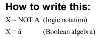
==NOT Gate==: Has only one input and output is 1 only if input is 0.
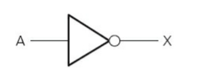
- Truth Table:
| Input | Output |
|---|---|
| A | X |
| 0 | 1 |
| 1 | 0 |
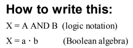
==AND Gate==: Two inputs. Output is 1 if both inputs are 1s.
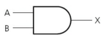
- Truth Table:
| Input | Input | Output |
|---|---|---|
| A | B | X |
| 0 | 1 | 0 |
| 1 | 0 | 0 |
| 0 | 0 | 0 |
| 1 | 1 | 1 |
^^Tip: Multiply the inputs.^^
==OR Gate==: Two inputs. Output is 1 when any of the inputs is 1.

- Truth Table:
| Input | Input | Output |
|---|---|---|
| A | B | X |
| 0 | 1 | 1 |
| 1 | 0 | 1 |
| 0 | 0 | 0 |
| 1 | 1 | 1 |
^^Tip: Add the inputs.^^
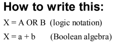
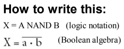
==NAND (NOT AND) Gate==: Two Inputs. Output is 1 if both inputs are not 1.
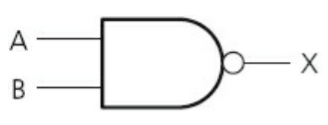
- Truth Table:
| Input | Input | Output |
|---|---|---|
| A | B | X |
| 0 | 1 | 1 |
| 1 | 0 | 1 |
| 0 | 0 | 1 |
| 1 | 1 | 0 |
^^Tip: Calculate for AND and write opposite output.^^
==NOR (NOT OR) Gate:== Two inputs. Output is 1 if neither input is 1

- Truth Table:
| Input | Input | Output |
|---|---|---|
| A | B | X |
| 0 | 1 | 0 |
| 1 | 0 | 0 |
| 0 | 0 | 1 |
| 1 | 1 | 0 |
^^Tip: Calculate for OR and write opposite.^^

==XOR Gate==: Two inputs. Output is 1 if inputs are not same.
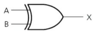
- Truth Table:
| Input | Input | Output |
|---|---|---|
| 0 | 1 | 1 |
| 1 | 0 | 1 |
| 0 | 0 | 0 |
| 1 | 1 | 0 |

Logic Circuits
Multiple Logic gates make up a ==Logic Circuit.==
Complex operations are performed through them.
Truth tables are made to check outputs, and all inputs are considered.
To make a truth table, it is easier to divide the circuit into parts and name all the outputs at each stage.Example:
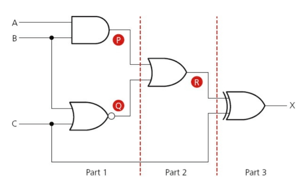
| Input A | Input B | Input C | Output P | Output Q | Output R | Output X |
|---|---|---|---|---|---|---|
| 0 | 0 | 0 | 0 | 1 | 1 | 1 |
| 0 | 0 | 1 | 0 | 0 | 0 | 1 |
| 0 | 1 | 0 | 0 | 0 | 0 | 0 |
| 0 | 1 | 1 | 0 | 0 | 0 | 1 |
| 1 | 0 | 0 | 0 | 1 | 1 | 1 |
| 1 | 0 | 1 | 0 | 0 | 0 | 1 |
| 1 | 1 | 0 | 1 | 0 | 1 | 1 |
| 1 | 1 | 1 | 1 | 0 | 1 | 0 |
In order to make a Logic Circuit from a Logic statement, mark all the gates in the statement, and always mind the brackets.
To make a logic circuit from Boolean or Logic statements, make different parts of the circuit and then join them using gates which connect the brackets.
Some logic gates can make a whole logic circuit and any other logic gate. They are known as ==Building Blocks==. NAND gate, for example, can make an AND gate:

Logic circuit can also be simplified. Just like the circuit above can be simplified to just one AND gate.
Note: When one input branches into two before entering a gate, the two branched inputs will ^^always^^ be same. 1,1 or 0,0.