Checking Amperage
Electrical Components
Electrical components in a circuit must draw a specific amount of current to operate properly.
Measuring the current flow in a circuit helps determine if an electrical device is functioning correctly.
Low current flow (low amperage reading): Indicates higher than normal resistance in the circuit.
High current flow (high amperage reading): Indicates lower than normal resistance in the circuit.
Amperage Measurements in Series and Parallel Circuits
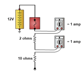
Series Circuit:
The same amount of current flows through every component in the circuit.
Amperage is equal at all points in a series circuit.
If one component opens (fails), the entire circuit stops conducting current.
Example: If the total current is 2 amps, every component in the circuit carries 2 amps.
Parallel Circuit:
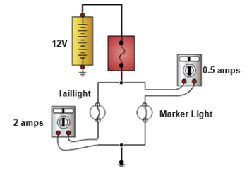
The total circuit current is the sum of the currents through each branch.
Each branch receives a portion of the total current based on its resistance.
Branches with lower resistance draw more current.
The total current measured at the power source equals the combined current of all branches.
Example: If one branch draws 2 amps and another draws 3 amps, the total current is 5 amps.
Reasons to Check Circuits for Amperage
Cranks Slowly
Battery Dies
Never place the leads of an ammeter across the battery or a load; it will either open the fuse or destroy the DMM.
Measuring Current Flow
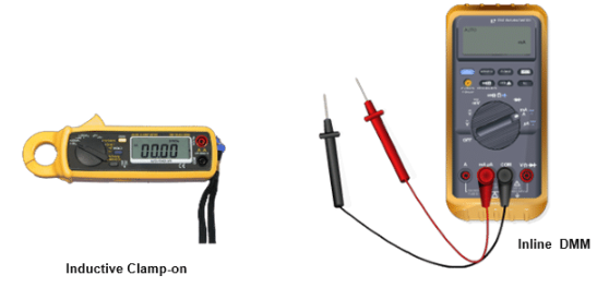
There are two methods:
Use an inductive clamp-on meter for high current flow
Use a DMM for low current flow
Don't use the DMM for measuring high current flow, or you risk damaging it
Steps to Measuring Amperage
Step 1
Determine the amount of current that can be expected in the circuit.
Step 2
Set the mode selector switch to the correct DC amperage setting (milliamps or amps).
Step 3
Connect the black test lead to the common (COM), or negative, input jack.
Step 4
After connecting the black test lead:
Connect the red test lead to either the amps or the milliamp or microamp port
Always use the highest rated amp port first
Step 5
After connecting the red test lead:
Prepare a fused jumper wire
Make sure the fuse has a rating that is less than the maximum allowable current
Step 6
Open the circuit at a point between the power supply and the load.
Step 7
Next:
Connect the DMM and fused jumper wire in series between the power supply and the load
This allows the current to flow through the DMM
Step 8
If applicable, turn on the DMM using the ON/OFF button on the meter.
Step 9
Finally:
The amperage measurement should display on the DMM
Use a clamp or current probe if the amperage exceeds the DMM rating