Electricity and Circuits (EdExcel)
Electric Charge
❂Objects can have positive or negative charges
❂ Like charges repel, opposite charges attract
❂ Electric charge is measured in coulombs
❂ Electric charges create electric fields in the areas surrounding them
❂ Field lines always go away from positive charges and towards negative charges
❂ Electrons are negatively charged particles
❂ Negative charges are the result of gaining electrons
❂ Positive charges are the result of losing electrons
❂ Conductors are materials that allow charge to pass through
❂ Insulators do not allow charge to pass through
Induction
❂ When a charged material is brought near an uncharged material, the charged material will induce a charge in the uncharged material
❂ If a negatively charged rod is brought near an object, it will attract positive charges towards the rod and the negative charges will gather on the opposite side
❂ Positively charged rod will attract negative charges
Current
❂ The flow of charge is known as current
❂ When two oppositely charged conductors are connected by a conductor, the charges will flow, producing a current
❂ The greater the flow of charge, the greater the current
❂ Current is the charge passing a point in a circuit every second
❂ Current = Charge/Time
❂ The unit of current is Amperes (A)
❂ Current can be measured using an ammeter
❂ Ammeters are always connected in series to the part of measurement
❂ The flow of free electrons in a metal causes current
❂ Electrons flow from negative to positive terminals
❂ Conventional current flows from positive to negative terminals
Electromotive Force
❂ The electromotive force is the work done in driving a charge around a complete circuit
❂ It is the potential difference across the battery
❂ It is measured in Volts (V)
❂ It is the energy per coulomb
Potential Difference
❂ Potential difference is the work done in driving a charge through a component
❂ It is measured in volts (V)}
❂ It is the energy per coulomb
❂ Potential difference can be measured using a voltmeter
❂ The voltmeter should be connect in parallel to the component of which the p.d is to be measured
Resistance
❂ Resistance is the opposition to current
❂ The higher the resistance, the lesser the current
❂ Potential Difference = Current x Resistance
❂ V = IR
❂ Resistance is measured in ohms
❂ To measure the resistance of a component, the current is measured by attaching an ammeter in series and potential difference is measured by attaching a voltmeter in parallel
❂ The readings are used to calculate the resistance by R=V/I
❂ Resistance is caused when the electrons flowing in a metal collide with the metal’s ions
❂ The longer the wire, the greater the resistance
❂ The greater the cross sectional area of the wire, the lesser the resistance
❂ Resistance is directly proportional to the length, and inversely proportional to the area
Ohm’s law
❂ Ohm’s law states that resistance is directly proportional to current when physical conditions such as the temperature are constant
❂ If the temperature varies, such as in a filament lamp, it will not obey ohm’s law
❂ Resistors that obey Ohm’s law are known as ohmic resistors
❂ Resistors that do not obey Ohm’s law are non-ohmic
❂ The IV graph of an ohmic graph is a straight line
❂ The graph of non-ohmic conductors is curved towards the voltage
❂ In non-ohmic conductors such as filament lamp, the temperature increases with time
❂ The temperature causes the resistance to increase
❂ A higher resistance means a lower current
Electrical Energy
❂ Energy is transferred from the power source to the components when current flows
❂ Energy transferred = Current x Voltage x time
Electrical Power
❂ Power is the rate of energy transfer
❂ Power = Current x Voltage
❂ P=IV
❂ The unit of power is Watt (W)
❂ Watt is the the same as Joules/second
❂ Energy = Power x Time
❂ E=Pt
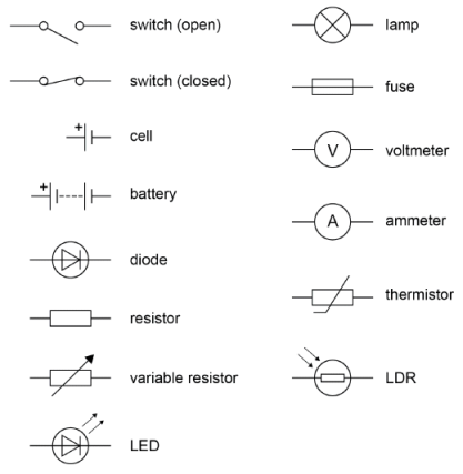
Circuit Symbols
Series Circuits
❂ Components are connected next to each other in series
❂ The current is same at all points in a series circuit
❂ The total EMF for batteries connected in series is the sum of their individual EMFs
❂ In a series circuit, the sum of the p.d of individual components is equal to the total emf
❂ If one component stops working, the whole circuit doesn’t work
❂ the total resistance in a series circuit is the sum of all individual resistances
Parallel Circuits
❂ The components are attached on separate branches
❂ Components can be individually controlled
❂ if one component stops working the rest will continue to function
❂ The current splits up in parallel circuits
❂ The sum of currents in each branch is equal to the emf
❂ The current does not split equally always
❂ The potential difference is same in every branch
❂ Resistors connected in parallel have decreased resistance
❂ If two identical resistors are attached in parallel, the resistance is will be half of one component
❂ The reciprocal of the total resistance is equal to the sum of the reciprocals of the individual resistors
❂ 1/Rt = 1/R1 + 1/R2 …+ 1/Rn
Potential Dividers
❂ When two resistors are connected in series, voltage is shared between them
❂ The larger resistance resistor will get greater potential difference
❂ Increasing the resistance of one resistor will increase the voltage across it and reduce the voltage across the other resistor
❂ A potentiometer consists of a coil of wire with a sliding contact
❂ Moving the sliding contact changes the resistance as it changes the length of the coil the current has to pass through
❂ Adjusting the slider can be used to control the voltage across components in series
Relay
❂ A relay consists of an electromagnet and a magnetic switch
❂ The switch is within the magnetic field range of the electromagnet
❂ When there is current in the electromagnet coil, it attracts the magnetic switch
❂ Attracting the switch closes it, allowing the current to pass through the circuit of the switch
❂ Turning the current off in the electromagnet turns the switch back open
Thermistor
❂ Thermistors are resistors that have variable resistance depending upon heat
❂ As the thermistor gets hotter, its resistance decreases
❂ As the thermistor gets colder, its resistance increases
❂ The temperature and resistance are inversely proportional
LDRs
❂ Light dependant resistors change resistance according to the light on it
❂ When more light shines on the LDR, the resistance decreases
❂ When the light is lesser, the resistance increases
Diode
❂ Diode is a component that allows current to pass in one direction only
❂ If the current direction is opposite to the diode, there will be no current
❂ It converts a.c current to d.c current
❂ There will be no current half the time with a.c current
Hazards of Electricity
❂ Electricity can be lethal, a few volts of shock can be hazardous
❂ Touching an exposed wire due to damaged insulation can cause an electric shock
❂ Passing too much current through a wire can cause overheating and lead to fires
❂ Moisture can come into contact with live wires in damp conditions, conducing electricity and causing a short circuit or even posing risk of electrocution
Fuses
❂ Fuses are a safety measure to cut off electricity to an appliance if the current is too large
❂ Fuses consist of a glass cylinder with a thin metal wire
❂ If the current is too large, the wire will heat up and melt
❂ The circuit will be broken and the current wont be able to pass through
❂ Fuses have different ratings which are decided by the power of the appliance
❂ The power of the component is found using P=IV
❂ The rating of the fuse is the next size up higher than the power rating
❂ The power should fall in the middle of the fuse’s range
❂ The fuse is attached on the live wire so that the current can not damage the device or cause shock
Earthing
❂ Electrical appliances can have metal cases which can cause hazards
❂ If a live wire comes into contact with the metal case, touching it would cause a dangerous shock
❂ The earth wire provides a low resistance path to the earth
❂ If the current becomes too large, it will cause a surge in the earth wire, blowing the fuse
❂ the fuse cuts off the supply of electricity, making the appliance safe