P2
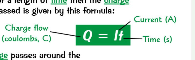
Current
This is the flow of the electrical charge Measured in amperes,
The grater the resistance the lower the current
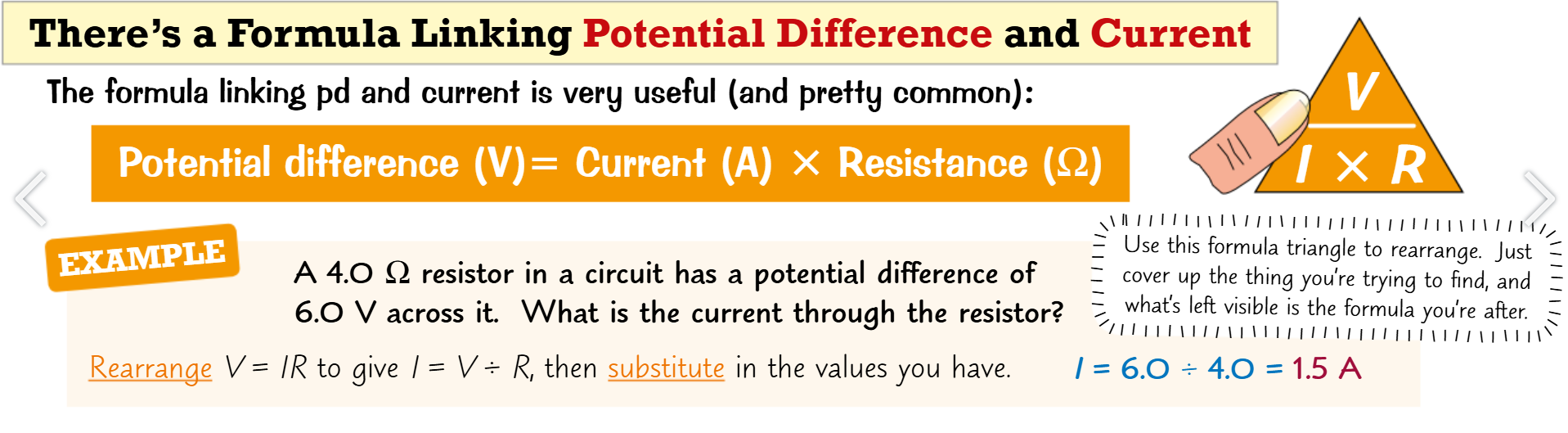
Potential difference:
What pushes charge around
Dependant on the resistance
Measured in voltage
Resistance
Ammeters measure current (Amps/ A) Must be in series
Voltmeters measure potential difference (P.D, Voltage/ V) Most be in parallel
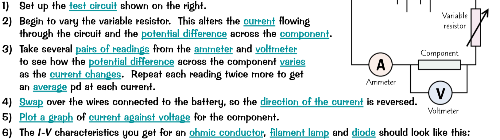
I-V Characteristics
IV characteristics refers to how current and P.D relate to each other on a graph. You can get the results for a graph by:
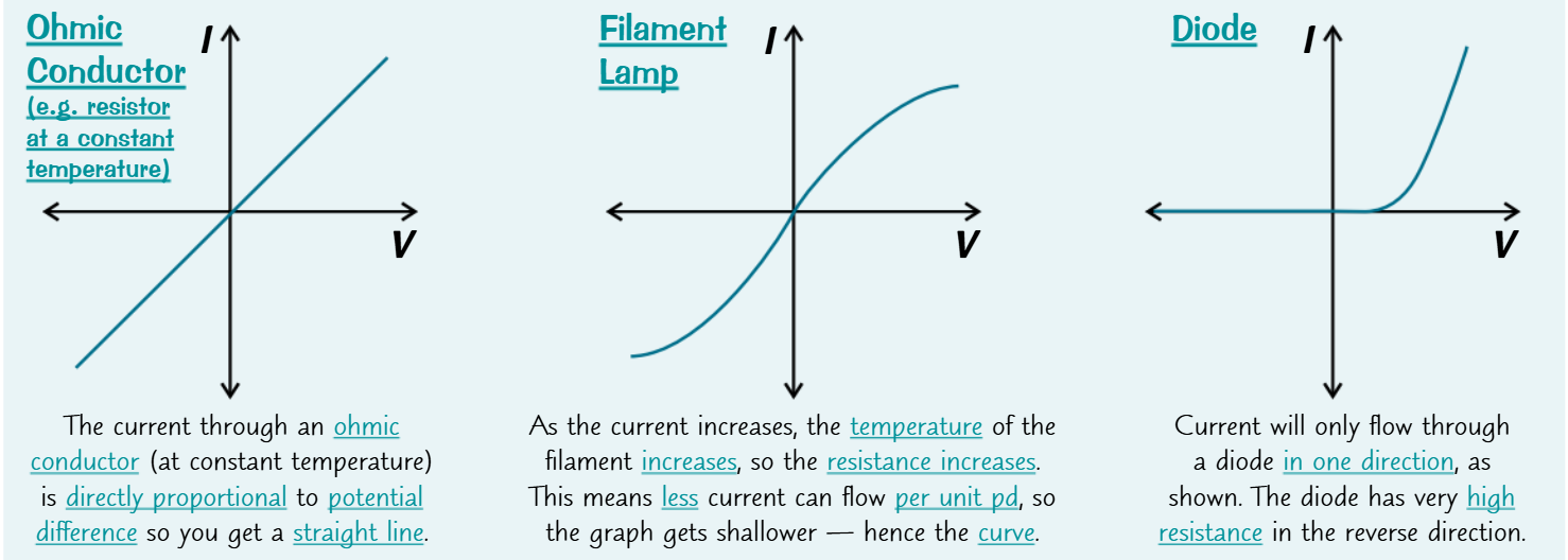
Now remember kids:
As the current increases the temperature increases
As the temperature increases so does the resistance, reducing the current on extreme ends
Diodes can only allow current in one direction
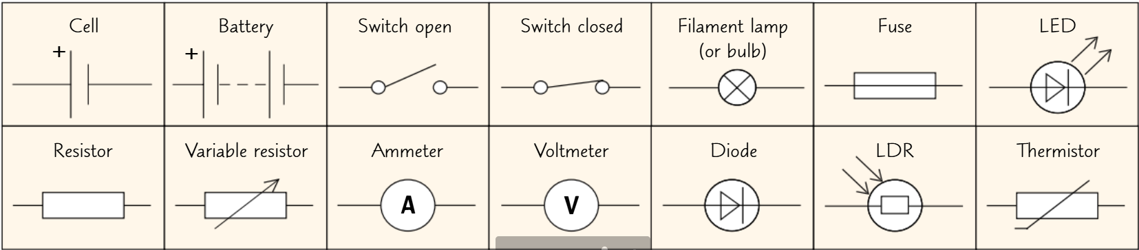
Circuit Devices
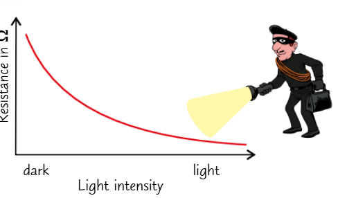
LDR:
As light increases resistance is low
In dark resistance is high
They can be used for automatic night lights or bugler detectors
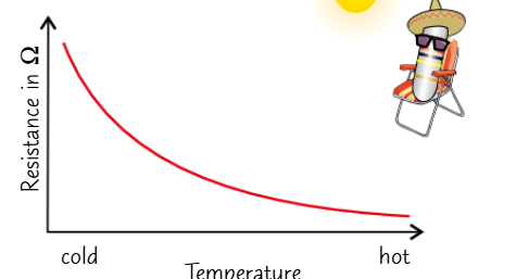
Thermistor:
low resistance in warm temperature
High resistance in call temperatures
Can be use as electronic thermostats or car engine temperature sensors
Ammeter:
Measures current in amps (A)
Has to be connected in series
Voltmeter:
Measures Potential Difference /P.D/ Voltage in Volts (V)
Has to be connected in parallel
The appliances could be used to make a sensory circuit e.g.:
If you connect a thermistor to a fan in a room so that when it gets too hot it turns on and when it cools down it turns off.
Or a bulb where an LDR is parallel to a bulb so when it gets dark the charge passes through the bulb instead of of the LDR
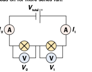
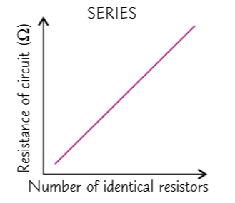
Series circuits
An end to end complete loop.
If one thing connected in series breaks or is disconnected, the entire thing stops working.
Potential difference is shared between individual appliances so Vtotal = V1 + V2 + …
Current is equally shared so at any given point the in the circuit current will be the same so I1 = I2 = …
The resistance of each appliance adds up to the total resistance, the more resistance an appliance has the more voltage it’ll get. so remember: Rtotal = R1 + R2 + …
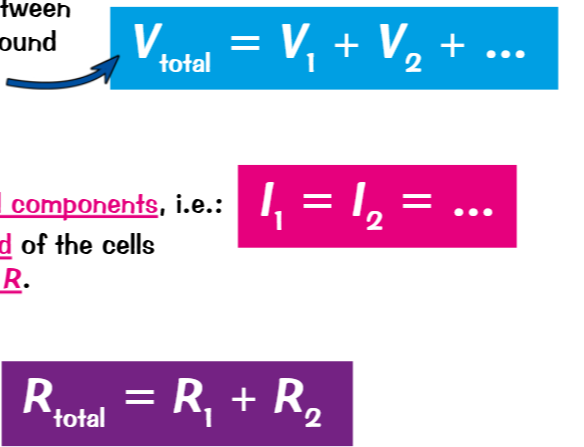
Parallel circuits
Each component is connected separately where current can flow in each branch independently.
Most things are connected like this e.g.:
cars
House hold electrics, but mainly most things are connected using a mixture of circuits
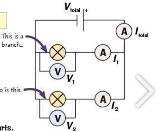
P.D:
Each component gets the same amount of p.d everywhere
So V1 = V2 = …
Current:
Current splits at junctions an leading to a component
And exits at junctions exiting from a components
Current is split unevenly between each component
So Itotal = I1 + I2 + …
Since electrons take the path of least resistance
So the majority of current will go the the layer with the least resistance
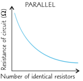
Resistance:
This will always be less than the smallest resistors resistance
E.g.: If the lowest parallel resistor is 2 ohms
The total resistance will be less than 2 ohms
Or >2ohms
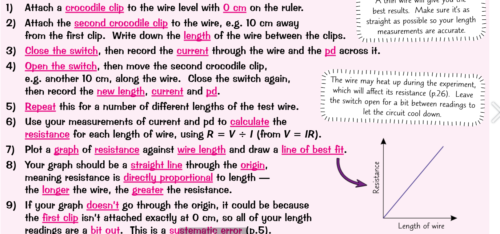
Investigating resistance
You can do this by:
Making note of the Voltage of the battery
Measure the current using an ammeter
Calculate resistance
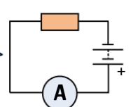
Add another resistor or increase the resistance on a variable resistor
Measure the current again
Calculate resistance again
Repeat until you have added all resistors or increased to max setting
Plot on graph
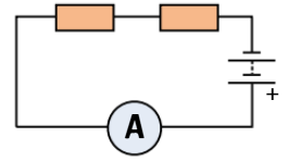
Your results in series should show that adding resistors more or less proportionally decreases the current like so:
You can do the exact same thing again only the resistors are in parallel:
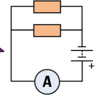
You should observe an overall decrease in resistance as the number of identical resistors increases.
Electricity at home
There are 2 types of current:
Alternating current (AC)
~ In which the Voltage alternates and the positive and negative ends alternate (swap/ change frequently)
~ In UK homes the voltage is usually 230V alternating at 50 cycles per second (50 Hz)
DC:
~This is just straight forward current that flows in the same direction and has a direct voltage
Inside the black or white cables we see there are usually 3 wires coated in colour plastic which tells us their jobs you have:
Brown/ red live wire:
Which Has the alternating 230V current from the mains supply
It is where electricity flows in
The blue neutral wire:
Which has Voltage of 0 and usually completes the circuit
It is where electricity flows out
Carries away current
The green and yellow Earth wire
For safety
Stops appliance casing from becoming live
0V
0 current
The ground acts as a reservoir of positive ions and charges
Electricity is negatively charged as it is the flow of electrons
So as opposite charges attract
When electricity is given a low resistance path to go to the ground
It rushes through it to the ground
So say if a charged component like a live wire was touched by someone
Who happens to also be touching the ground
There is a large potential difference in voltage between you and the socket
causing the charge to flow through you in a current, towards the ground
This applies to sockets which are even switched off as they still have a high P.D
Simply put when a link is made between electricity supply and earth, current flows through that link to the earth, and that can damage things
Power and electricity
The charge in a circuit does work against resistance to transfer energy into an appliance, which acts as an energy transfer:
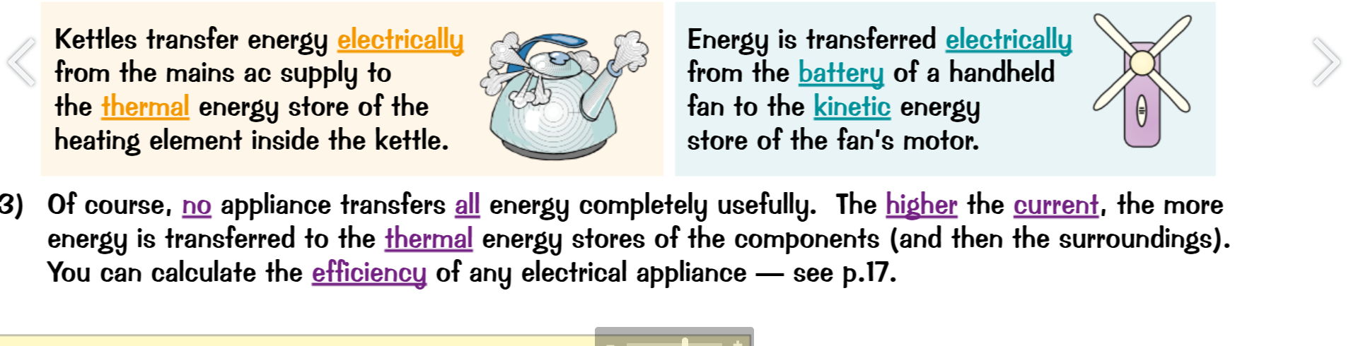
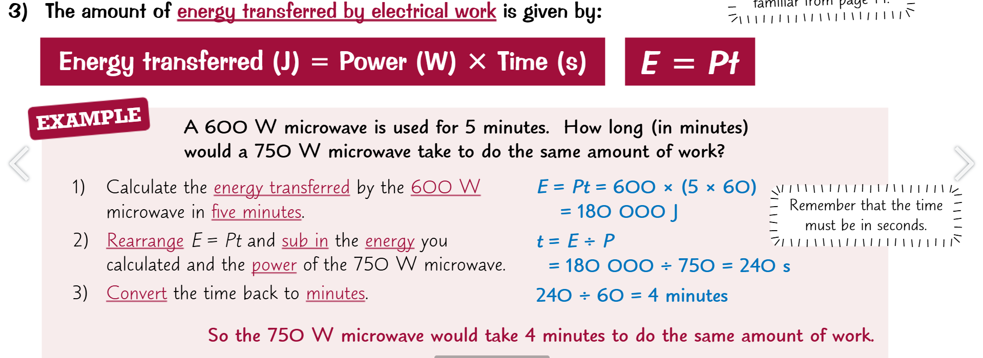
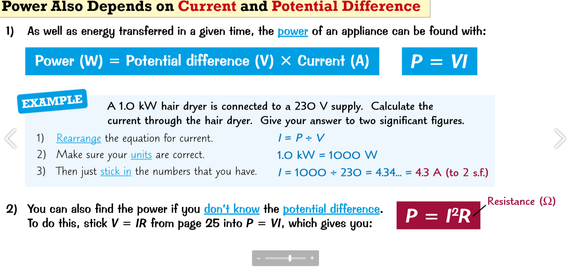
Since power = energy transfer over time:
Appliances are often given a power rating: Their maximum safe power output
Higher power models are more expensive to run however work faster
However power doesn’t equal efficiency so some higher power models may actually be more inefficient than lower power models
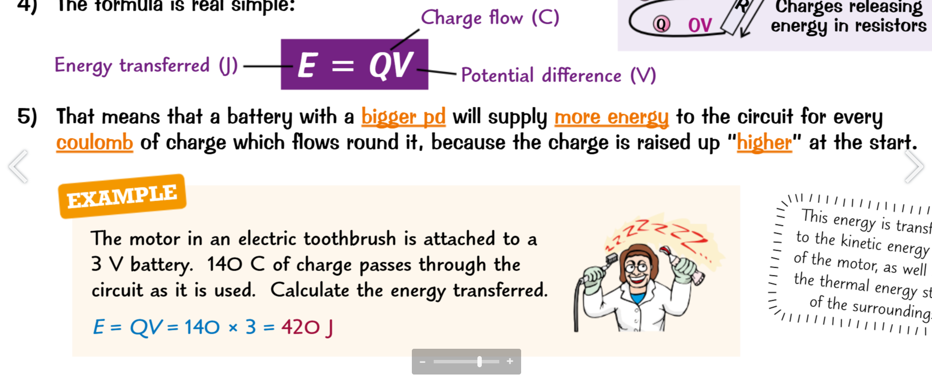
Work is done against resistance to push charge with potential difference, So think of the Voltage as the pushing force and the charge flow as the weight. As if someone is pushing a heavy stone: The voltage is pushing a charge flow, which transfers energy. So:
Also:
The National Grid
This is the UKs system of Power stations, cables and transformers that supply the general population with electricity. These power stations need to be able to predict and deal with changes with demand e.g. when people go on holiday, when work finishes, when a large sporting event is happening, a festival etc.
How they operate:
They operate with an extremely high P.D. at around 400,000V and a low current
Since a high current is very expensive to produce and would heat up the wires
Making them unsafe and increasing resistance, making the wires waste lots of energy
Transformers will usually step up the P.D. to 400,000 for efficient transmission over long distances
Then step down the P.D to usable levels safe for domestic use
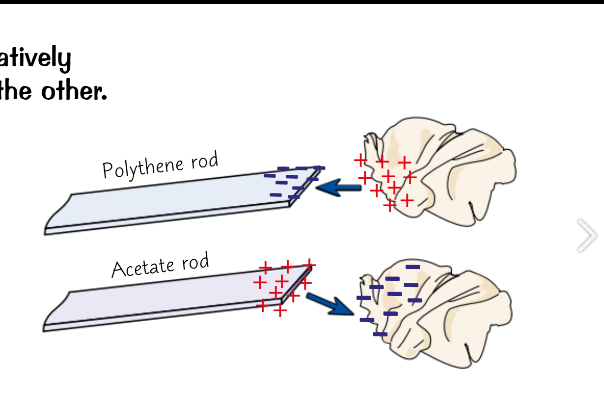
Static electricity
When certain insulating materials are rubbed together electrons are scrapped off of one and dumped onto another
Leaving you with a positively charged surface and a negatively charged surface
The direction of movement of electrons depends on the materials used
Now electrons are the only one that can move meaning that the sparks will always come from negative sources:
This happens when the potential difference between the negatively charged object gets high enough that electrons can jump across a small gap towards an earthed conductor.
Which is basically just damn near anything/one providing a pathway to the ground.
Electrical fields
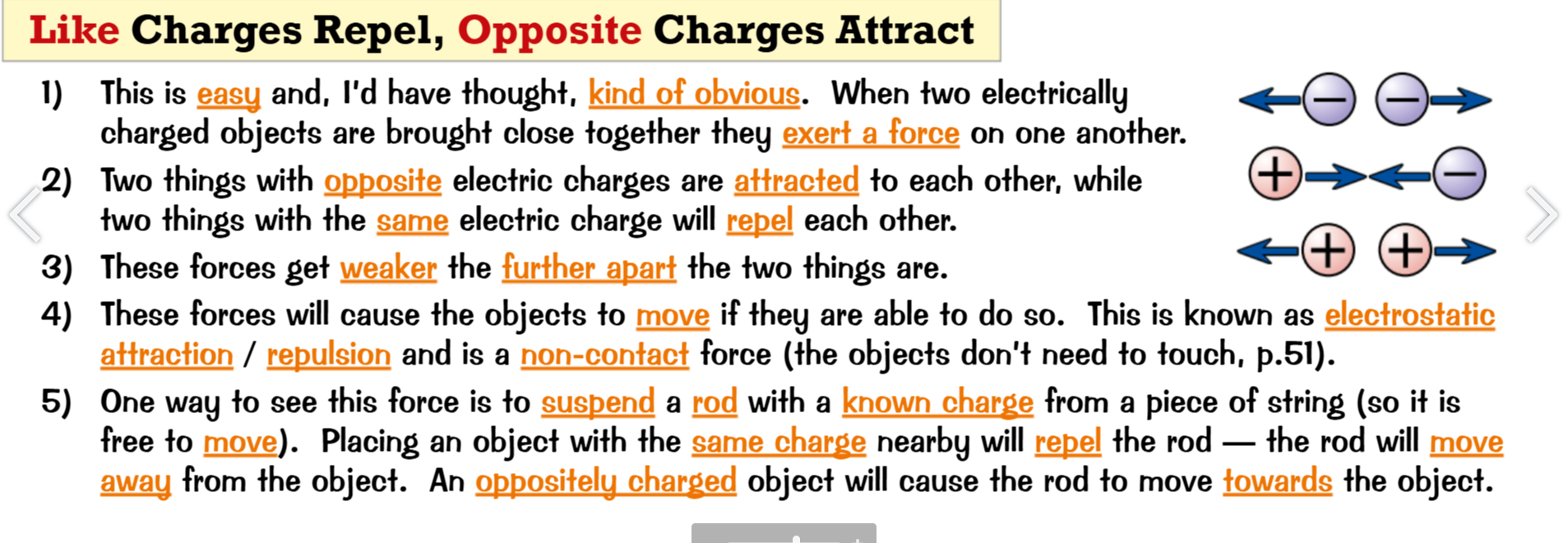
An electrical field is the field around a charged object in which a force is exerted on other charged objects
The closer you get to it the stronger its effect/ force
Field lines show the direction of the force exerted by the electrical field and are always perpendicular to the surface of a charged object
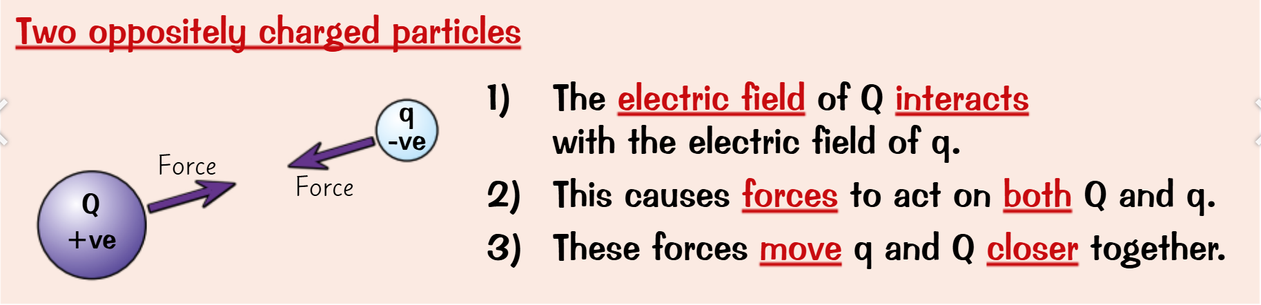
The force exerted by an electrical field comes from 2 fields interacting with each other
A high enough P.D causes an electrical field
A strong enough electrical field can cause electrons to be removed from the air
Ionising the air
this ionised air can now carry a current/ charge
This causes a spark as current passes through it in an attempt to reach the ground using air as an earthed conductor
P2 finished