Locking Hubs
Manual Locking Hub Components
Knob
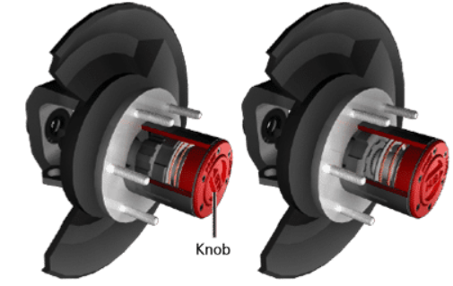
The locking hub knob has two positions: free/unlock and lock.
In the free/unlock position, the hub rotates independently of the axle shaft.
When turned to the lock position, the hub and axle shaft engage, allowing power from the differential to transfer to the wheels.
Changing the knob position requires the vehicle to be stopped, and the driver must manually adjust it.
In the locked position:
The knob rotates with the hub.
The hub is engaged to the axle shaft, enabling torque transfer.
Clutch
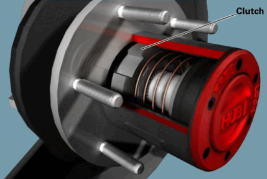
The manual locking hub clutch moves when the knob is turned to the lock position, engaging the hub to the axle shaft.
When the knob is turned to the free/unlock position, the clutch slides back, releasing the hub from the axle shaft.
This allows the wheels to rotate independently of the axle shafts.
The manual locking hub clutch:
Applies pressure to the hubs.
Engages to lock the components together.
Hub Body
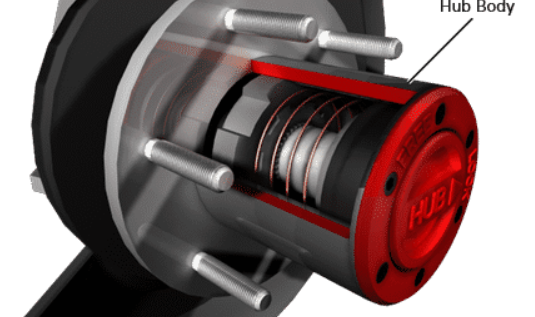
The hub body houses the knob and clutch, forming a complete locking hub assembly.
This assembly bolts to the hub of the front brake rotor on the vehicle.
The metal hub body is usually painted or treated to resist corrosion.
A gasket or O-ring seals the hub body to the brake rotor, preventing leaks and contamination.
Automatic Locking Hub Components
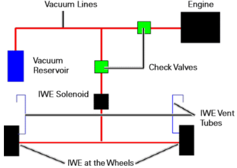
Vacuum Reservoir, Hoses, and Check Valve
Engine vacuum is stored in the vacuum reservoir, which supplies the IWE (Integrated Wheel End) system.
A check valve separates the IWE system from other engine components, ensuring the IWE remains disengaged if another system experiences a vacuum leak.
Hoses connect the IWEs, left and right steering knuckles, and the vacuum reservoir.
Vent hoses on the IWE allow the diaphragm to expand and contract during operation.
Together, the vacuum reservoir, hoses, and check valve maintain the correct pressure within the automatic locking front hub system.
IWE Solenoid
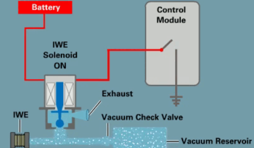
Switched battery voltage provides power to the IWE solenoid.
The control module supplies a ground to the solenoid when the driver selects 2WD high.
In 2WD, engine vacuum passes through the solenoid to disengage the IWEs.
When the driver selects 4WD, the control module releases the ground, allowing the existing vacuum to exhaust from the IWEs through the solenoid.
IWE Spring-loaded Vacuum Hubs
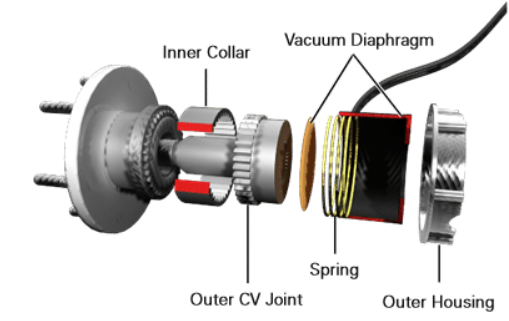
IWE (Integrated Wheel End) spring-loaded vacuum hubs include:
An outer housing that bolts to the steering knuckle
A vacuum diaphragm
An internal spring
An inner collar with internal splines
The inner collar splines onto the outer CV joint housing.
When vacuum exhausts from the IWE, the internal spring pushes the collar to engage the splines on the wheel hub, connecting the axle shaft to the wheel hub.
If a vacuum leak occurs while in 2WD, a grinding noise may occur as the collar attempts to engage the hub without torque from the transfer case.
Front Axle Disconnect
Vacuum Disconnect
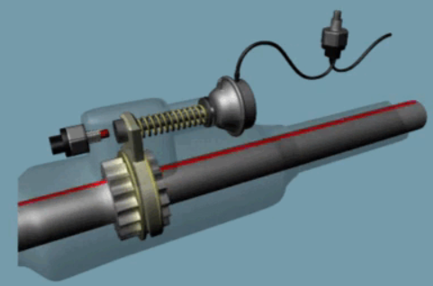
When four-wheel drive is selected, a vacuum switch on the transfer case opens.
The switch directs engine vacuum to the vacuum shift servo, which pulls the shift fork.
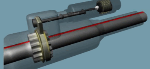
The sliding shift fork engages the shift collar, connecting the intermediate axle shaft to the outer axle shaft.
This locks both axle shaft sections together, allowing power from the transfer case to be transmitted to the front wheels.
Electronic Disconnect
The electric disconnect engages when the driver selects four-wheel drive.
The transfer case control module signals the electric motor actuator to extend the plunger.
The plunger moves the clutch fork and sleeve, locking the two axle shafts together.
When two-wheel drive is selected, the control module signals the actuator to retract the plunger.
This slides the clutch fork back, disconnecting the two shafts.