Magnetism
Units
ampere (A): unit of electric current, measuring the rate of flow of electric charge in a circuit; 1 ampere means 1 coulomb of charge passes a point each second
volt (V): unit of potential difference, equal to the energy transferred per unit charge; 1 volt = 1 joule per coulomb
watt (W): unit of power, measuring the rate of energy transfer; 1 watt = 1 joule per second
Magnetism
Properties of Magnets
Magnets have two poles: north and south.
Like poles repel, unlike poles attract.
The force between magnets acts at a distance through a magnetic field.
Magnets attract magnetic materials such as iron, steel, nickel, and cobalt.
The magnetic force is strongest at the poles of a magnet.
Magnetically Hard and Soft Materials
Magnetically hard materials:
Difficult to magnetise but retain magnetism for a long time.
Have high coercivity (resist demagnetisation).
Used to make permanent magnets (e.g. steel).
Magnetically soft materials:
Easy to magnetise but lose magnetism quickly when the field is removed.
Have low coercivity.
Used in electromagnets and transformer cores (e.g. iron).
Magnetic Field Lines
A magnetic field is a region where a compass will align/ is a region where a magnetic material will experience a force
Magnetic field lines represent the direction and strength of a magnetic field.
They point from the north pole to the south pole outside the magnet.
Inside the magnet, they go from south to north, forming closed loops.
The closer the lines are, the stronger the magnetic field.
Field lines must never cross or touch, as this would imply two directions at once.
The stronger the field, the closer togther the lines are
Induced Magnetism
When a magnetic material is placed in a magnetic field, it can become magnetised.
This happens because domains (regions of aligned atoms) align with the field.
In soft materials, this effect is temporary.
In hard materials, some magnetism may remain after removal of the field.
Magnetic Field Patterns (Practical)
Iron filings can be sprinkled around a magnet to reveal field patterns.
A plotting compass can be used to trace field lines and direction.
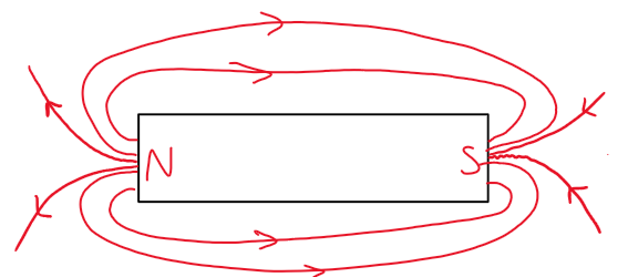
Around a bar magnet: curved lines from north to south.
Between two magnets:
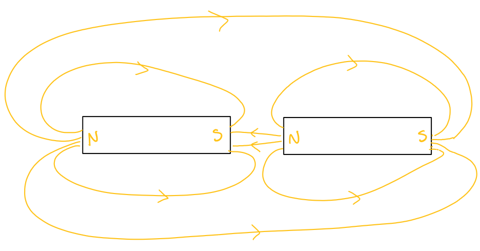
Opposite poles: field lines connect, showing attraction and a strong field.
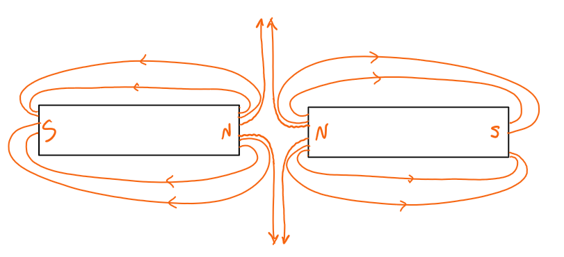
Same poles: field lines push apart, showing repulsion and a weaker region between them.
The density of filings indicates field strength.
Uniform Magnetic Field
Produced by placing two flat, parallel magnets with opposite poles facing each other.
Field lines are straight, parallel, and evenly spaced.
This shows the magnetic field has constant strength and direction throughout the region.
Uniform fields are useful in experiments where a constant force is needed.
Different magnet examples
Single bar magnet:
2 bar magnets - North poles facing towards each other:
2 magnets - opposite poles facing:
Electromagnetism
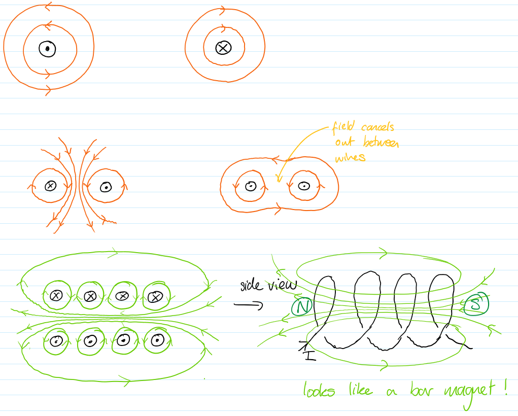
Magnetic Field Around a Current
A current flowing through a conductor produces a magnetic field around it.
The field consists of concentric circular lines centered on the wire.

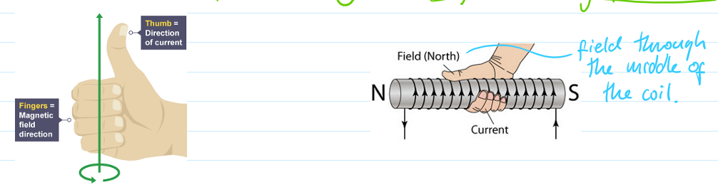
The direction of the field can be determined using the right-hand grip rule (thumb = current, fingers = field direction).
Increasing current increases the strength of the magnetic field.
Summary:
Electromagnets
Made by wrapping insulated wire into a coil (solenoid) around a soft iron core.
Makes the magnetic field stronger
Uses iron because it can be turned on and off whereas steel would stay magnetic
When current flows, the coil produces a magnetic field similar to a bar magnet.
The soft iron core becomes magnetised, greatly increasing field strength.
Strength can be increased by:
Increasing current
Increasing number of turns
Using a better core material (soft iron)
Can be switched on and off, unlike permanent magnets.
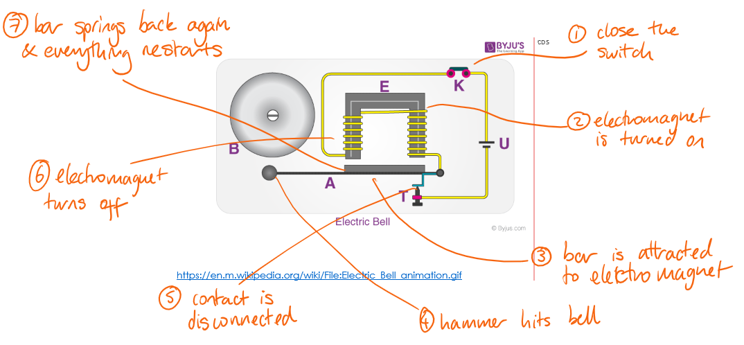
Electric bell:
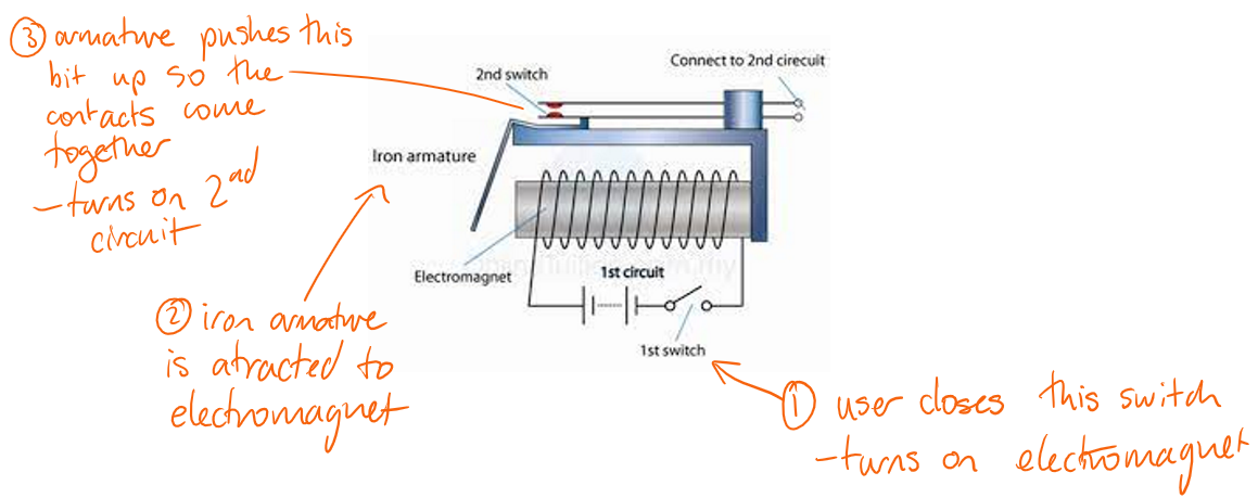
Relay:
A relay is a magnetic switch and they are used for turning on high current or dangerous appliances so that the user stays away from the danger
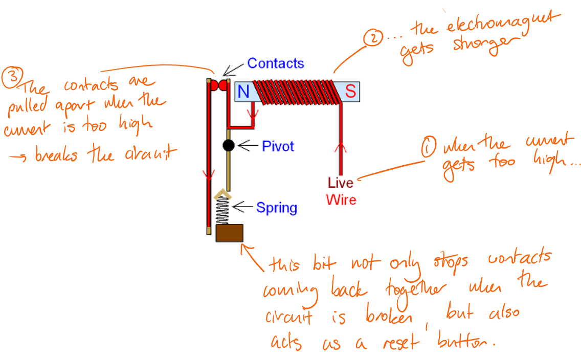
Circuit breaker:
Magnetic Field Patterns
Straight wire: circular field lines around the wire, closer near the wire indicating stronger field.
Flat circular coil: field lines loop through the coil, resembling a weak bar magnet.
Solenoid:
Inside: strong, uniform, parallel field lines.
Outside: weaker, curved lines similar to a bar magnet.
Force on a Charged Particle
A charged particle moving through a magnetic field experiences a force.
The force acts perpendicular to both the direction of motion and the magnetic field.
If the particle moves parallel to the field, no force acts.
This can cause circular or curved motion of charged particles.
Catapult field:
What is the combined magnetic field for a wire and a uniform field?
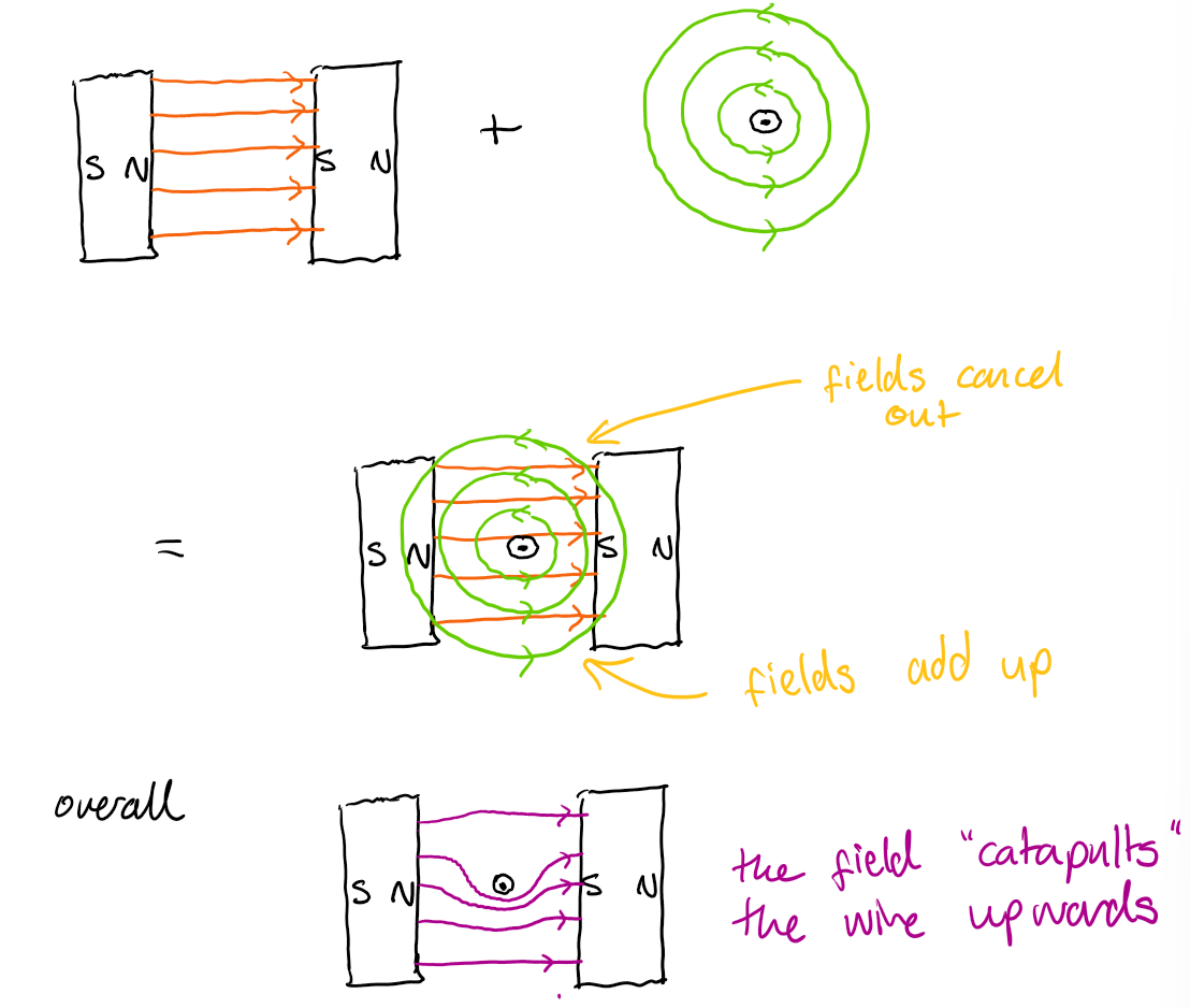
Force on a Current-Carrying Wire
A wire carrying current in a magnetic field experiences a force due to interaction between magnetic fields.
This is called the motor effect.
The force is perpendicular to both current and magnetic field direction.
Applications:
d.c. motors: convert electrical energy into kinetic energy (rotation).
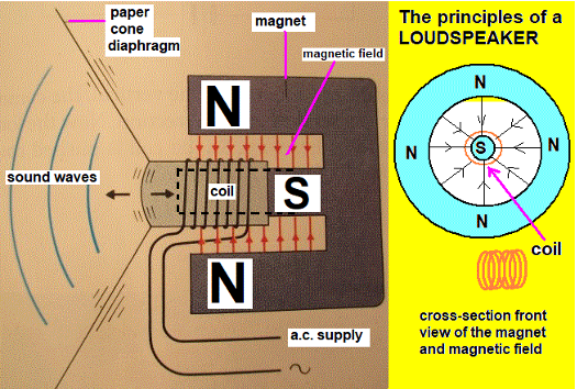
loudspeakers: convert electrical signals into vibrations (sound).
Speaker:
When the current flow one way round the speaker coil, the speaker moves left
When it flows the other way round the speaker moves right
Use Fleming’s left hand rule to work out which way it will move
Just focus on one point of the could to work out the direction
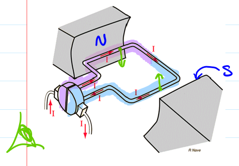
Motors:
Motors spin anticlockwise
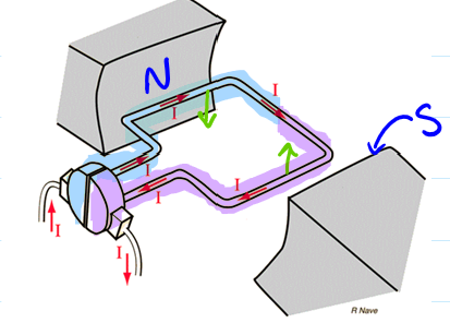
Half a turn later - the could as turned over so now the current in the purple half is flowing left instead of right
This keeps the motor spinning anticlockwise
Parts of a motor:
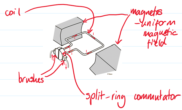
Coil - acts as the current carrying wire in a magnetic field so there is a force
Magnets - provide the magnetic field
Brushes - transfer current into the col without wires getting tangled up
Split-ring commutator - keeps the current flowing back on the left hand side and forwards on the right hand side so the motor keeps spinning the same way
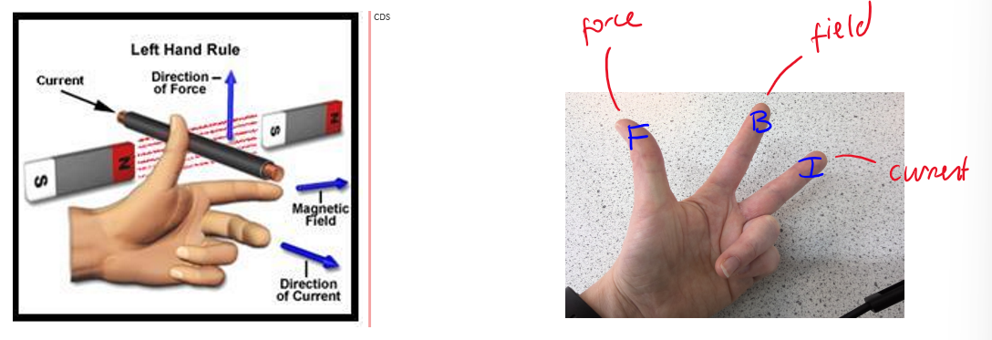
Left-Hand Rule
Used to determine direction of force on a current-carrying conductor.
First finger: direction of magnetic field (north to south).
Second finger: direction of current (positive to negative).
Thumb: direction of force or motion.
Overall with each abbreviation for what every finger represent it spells out FBI (Force, Field, Current)
If a current is parallel to the field, there will not be a force!
Factors Affecting Force
Increasing current increases the force.
Increasing magnetic field strength increases the force.
Increasing length of wire in the field increases the force.
Reversing current or field reverses the direction of the force.
Electromagnetic Induction
Reminder:
Left hand rule and catapult effect:
If you have a current carrying wire in a magnetic field you get movement due to the force
Magnetic field + current = movement (e.g. motor)
Current (+movement) = magnetic field (electromagnet)
SO movement + magnetic field = current (generator)
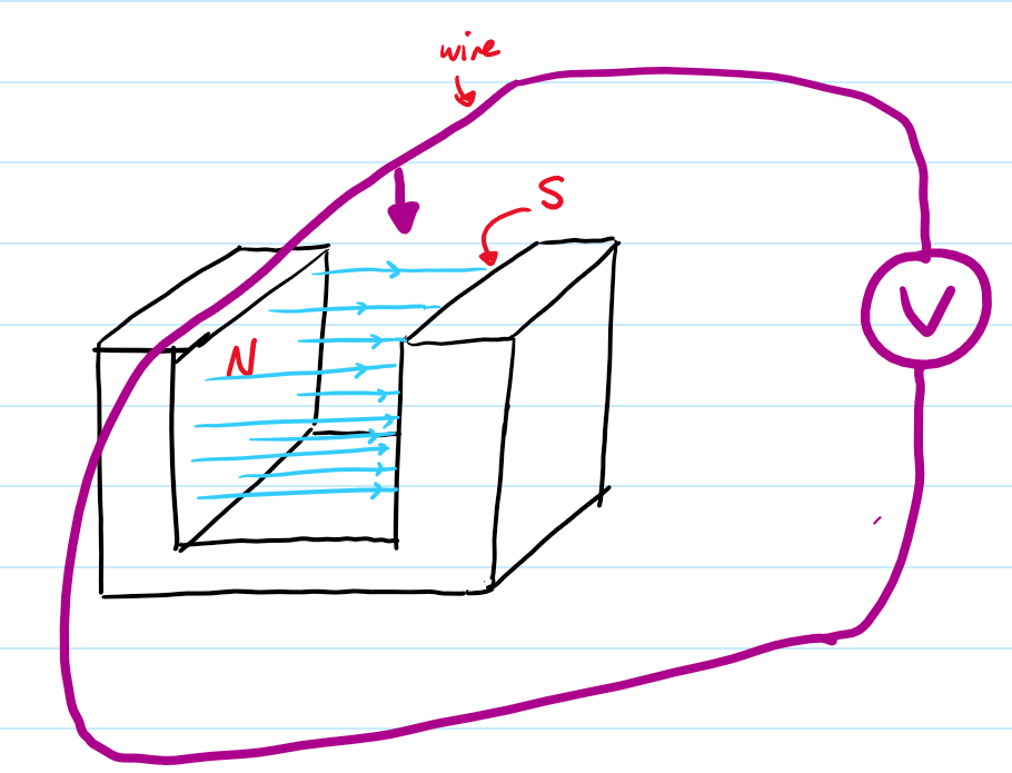
Induced Voltage
A voltage is induced when:
We move the wire into the magnetic field, it cuts the field lines
This generates induced voltage
As there will be a complete circuit, a current will flow
Other ways to get an induced voltage:
Move a magnet into a coil
Spin a magnet in a coil
Move a magnet out of a coil
Move a wire out of the magnetic field
Place a turned of electromagnet into a coil and then turn it on or off
Factors increasing induced voltage:
Faster relative motion
Stronger magnetic field
Greater number of turns in the coil
Larger area of the coil
Generating Electricity
Occurs when mechanical energy is converted into electrical energy.
Methods:
Rotating a magnet inside a stationary coil
Rotating a coil within a magnetic field
Produces alternating current (a.c.).
Increasing speed of rotation increases frequency and voltage.
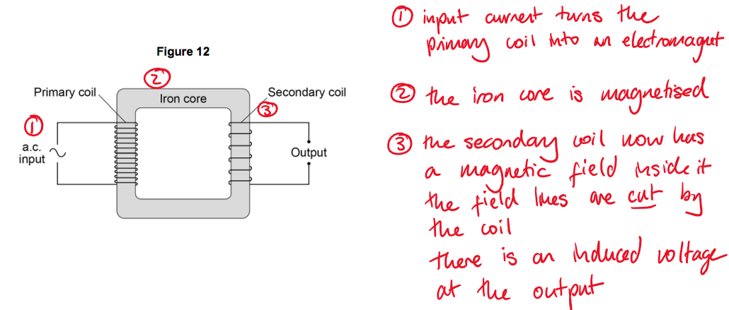
Transformers
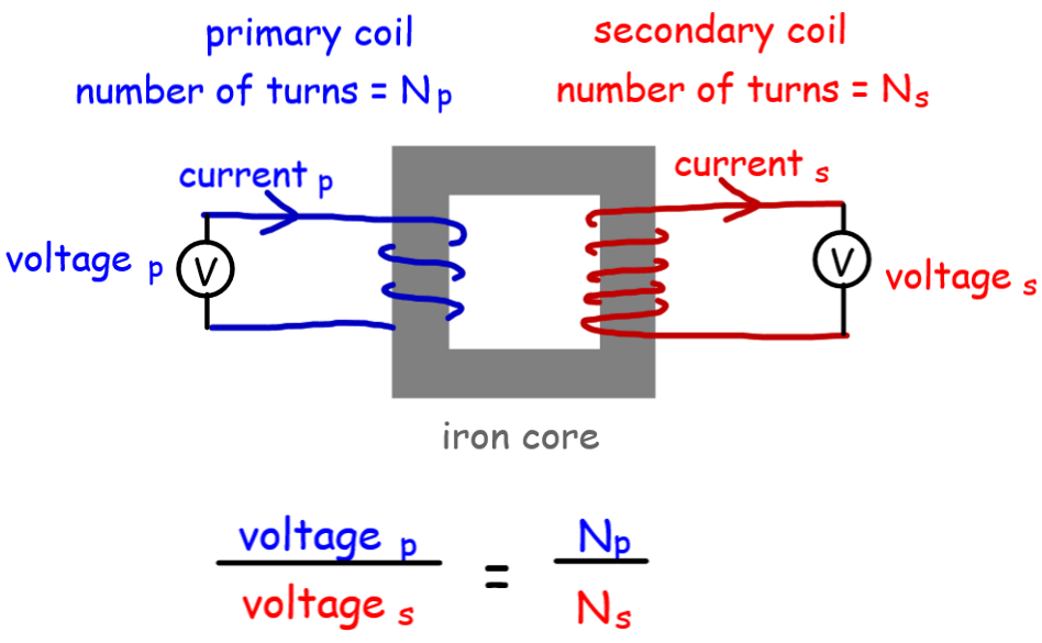
Consist of a primary coil, secondary coil, and an iron core.
The alternating current in the primary coil produces a changing magnetic field.
This induces a voltage in the secondary coil.
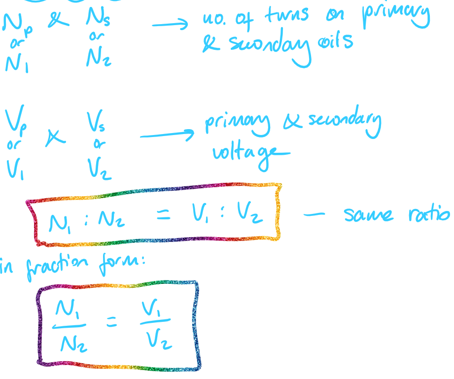
The size of the voltage depends on the number of turns in each coil.
Only work with a.c. because a changing magnetic field is required.
How do transformers work step by step
An alternating voltage is applies across the primary coil (the input)
The direction whihc the current flows though the primary coil therefore keeps reversing
This means that the current in the primary coil magnetises the iron core in one direction, then in the other, then back and so on
The magnetic field produced by the iron core there continually changes
As the field changes the magnetic field lines around the iron core move
These moving field lines cut through the wires in the secondary coil
This induces a voltage in the secondary coil
The direction in which the field lines move through keeps changing
The voltage is therefore induced in the secondary coil (the output) is an alternating voltage
Why transformers only work with a.c.
If a direct voltage is applied by the primary coil, then the iron core will be continually magnetised in the same direction
This means that the field produced by the iron core will not change
The magnetic field lines around the iron core will therefore be stationary and so will not cut the wires in the secondary coil
Meaning that no voltage will be induced in the secondary coil
Step-Up and Step-Down Transformers
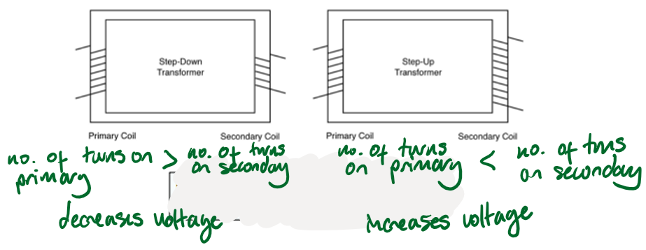
Step-up transformer:
Increases voltage
Secondary coil has more turns than primary
Step-down transformer:
Decreases voltage
Secondary coil has fewer turns than primary
Calculations:
National grid use:
Step-up transformers increase voltage for transmission to reduce energy loss (less current → less heating).
Step-down transformers reduce voltage to safe levels for homes and appliances.
Transformer Equation
input (primary) voltage / output (secondary) voltage = primary turns / secondary turns
Power in Transformers
input power = output power (for 100% efficiency)
Vp × Ip = Vs × Is

This means that if the voltage is increase by the transformer, the current will be decreased by the same factor
i.e. if voltage doubles, current will halve
Efficiency Considerations
In real transformers, some energy is lost as heat and sound.
Losses are reduced by using soft iron cores and insulating materials.