DLP Unit 5: Four Wheel Drive & All-Wheel-Drive Systems Service & Repair, Part 1
Four-wheel drive (4WD) systems include components not found in two-wheel drive (2WD) systems: a front drive axle assembly, transfer case, and front driveshaft.
The transfer case is mounted to the rear of the transmission.
The transfer case distributes engine power to both the front and rear axles, allowing all four wheels to receive torque.
A front and rear driveshaft connect the transfer case to their respective drive axles.
In 2WD mode, only the rear axle provides power to drive the vehicle.
When 4WD is engaged, the front axle assists the rear axle in driving the vehicle.
4WD systems use automatic, electronic, or vacuum-operated controls to engage the front axle.
Diagnosing 4WD systems is more complex than 2WD because they have additional rotating and control components.
During diagnosis, it’s important to determine whether the issue is mechanical or control-related.
Before starting a visual inspection, always review the service information to understand the system’s operation and control components.
First Order Of Vibrations
First-order vibrations are vibrations that occur at vehicle speed.
Driveshaft-related vibrations typically match the speed of the vehicle.
When a road test reveals a vehicle-speed vibration, the driveshaft or related components are likely the cause.
During diagnosis, inspect the driveshaft, pinion, pinion flange, and transmission output shaft, since all these components rotate at the same speed.
To diagnose a first-order vibration, measure vertical end play at the pinion flange and output shaft using a dial indicator.
Push up and pull down on the components to measure movement.
Check service information for exact end play specifications — some manufacturers provide them, others do not.
As a general rule, more than 0.010 in. of vertical end play is considered excessive.
Measure driveshaft runout at both ends of the driveshaft with a dial indicator.
Perform the check with the vehicle in NEUTRAL so the driveshaft turns freely.
On vehicles with multiple driveshafts, take measurements at several points.
Typical driveshaft runout limits are:
0.030 in. at the front and rear,
0.025 in. at the middle.
If the driveshaft is within specifications, check for runout at the:
Pinion flange — should not exceed 0.010 in.
Output shaft and stub shaft — should not exceed 0.005 in.
Always refer to service information for the exact specifications.
Second Order of Vibrations
Second-order vibrations occur twice per driveshaft revolution (two disturbances for each complete rotation).
To diagnose second-order driveshaft vibrations, perform the following checks:
Verify trim height:
Trim height affects how well the driveshaft transfers torque.
Changes from heavy loads, suspension modifications, or towing can alter trim height and driveline angles.
Incorrect angles prevent proper acceleration/deceleration cancellation, leading to second-order vibrations.
Inspect powertrain mounts:
Worn, collapsed, or misaligned mounts can shift the powertrain position.
This changes driveshaft working angles and can cause vibrations.
Check U-joints:
Each U-joint speeds up and slows down twice per driveshaft revolution.
Worn or failed U-joints often cause second-order vibrations, producing noticeable speed fluctuations or noise.
Verify driveshaft phasing:
Incorrect phasing disrupts U-joint motion balance and causes vibrations.
On one-piece driveshafts, out-of-phase conditions often mean the shaft is twisted and must be replaced.
On multi-piece driveshafts, the sections may need to be realigned and reinstalled in proper phase.
Confirm driveshaft working angles:
Incorrect working angles prevent proper U-joint acceleration/deceleration cancellation.
Adjust the angles by shimming the axle or transmission mount as needed to meet specifications.
Measure ring gear runout and bearing preload:
Internal axle issues like a bent pinion shaft, excessive pinion bearing preload, or improperly machined axle housings can also cause second-order vibrations.
Check that ring gear runout and bearing preload are within manufacturer specifications.
Third-order of Vibrations
Third-order vibrations occur when there are three disturbances per complete driveshaft revolution.
These vibrations are very rare in driveshafts.
Driveshafts equipped with constant velocity (CV) joints may experience third-order vibrations when:
A CV joint is worn, damaged, or failing.
The driveshaft working angles are not within specification, causing improper CV joint operation.
Always inspect CV joints and verify working angles when diagnosing a third-order vibration concern.
Forth-order of Operations
Fourth-order vibrations occur when there are four disturbances per complete driveshaft revolution.
These vibrations are very rare in driveshaft systems.
When a vibration is higher than third-order, the drive axle is often the source.
To diagnose, measure and inspect the following:
Bearing preload
Backlash
Ring gear runout
Abnormal readings in these areas can indicate internal axle issues that cause high-order vibrations.
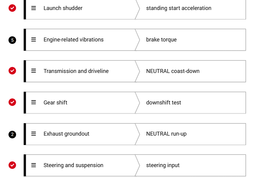
Slow acceleration test:
Gradually accelerate from a stop until the vibration occurs.
Helps determine if the vibration is speed-related or connected to acceleration forces.
Neutral coast-down test:
Drive past the vibration speed, shift into NEUTRAL, and allow the vehicle to coast down through the vibration range.
If the vibration remains in NEUTRAL, it may not be caused by the transmission or driveline.
Downshift test:
Bring the vehicle to the speed where vibration occurs, then downshift while maintaining that speed.
Helps identify if the vibration is related to a specific gear range.
Neutral run-up test:
With the vehicle in NEUTRAL, increase engine rpm without load.
Used to diagnose engine-related vibrations.
Brake torque test:
While holding the brake, increase engine rpm to apply load.
Helps detect engine vibrations under load, such as exhaust contact or mount issues.
Standing start acceleration test:
From a complete stop, accelerate normally to reproduce a launch shudder (vibration felt briefly at takeoff).
Steering input test:
Drive at the vibration speed and turn the steering wheel left and right.
Used to determine if steering or suspension loading affects the vibration.
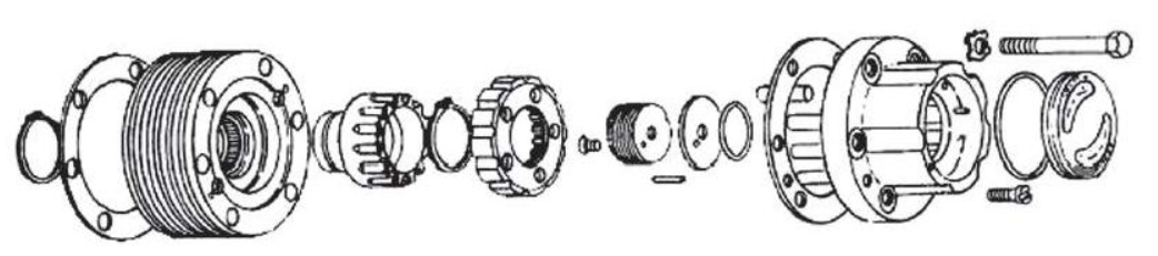
A lockout front axle hub (or locking hub) is a clutch mechanism that engages or disengages the front drive axle shafts from the wheel hub.
When locked, the hubs connect the front axle shafts to the wheels, enabling four-wheel drive operation.
If locking hubs malfunction, the axle shafts cannot engage the front wheels.
There are two main types of locking hubs used in 4WD vehicles:
Manual locking hubs: require the driver to turn a dial to engage the front axle shafts.
Automatic locking hubs: engage automatically without driver input.
When diagnosing 4WD issues, begin with a visual inspection of the front axle hubs before disassembly:
Inspect the outer housing and control assembly for mud, debris, or damage.
Verify that manual hubs are in the locked position—a freewheel position prevents engagement.
If needed, remove the hub cover to inspect internal components for the following issues:
Water or corrosion in the locking mechanism causing the clutch ring to stick.
Improper lubrication or thickened grease in cold conditions preventing engagement/disengagement.
Damaged or improperly installed fasteners.
Distorted snap ring, allowing excess movement and poor function.
Spline wear or damage on the axle shaft hub, ring clutch, or clutch body.
Broken, damaged, or collapsed springs.
Disconnected or loose vacuum lines on vacuum-operated hubs.
Proper inspection and correction of these conditions help ensure reliable 4WD engagement and operation.