Electricity
CURRENT RESISTANCE AND POTENTIAL DIFFERENCE
Current and Charge
Current is the flow of electrons around a circuit AND the flow of charge in a circuit
Current is measured in amperes/amps (A).
For charge to flow, a switch must be closed to create a closed circuit.
Electrical charge can be found by using the equation Q(C) = I(A) x T(s)
Current Potential difference and resistance
Resistance is known as the opposition to current, so the higher the resistance, the lower the current.
Additionally potential difference also affects the current, so the higher the potential difference the higher the current.
Resistance can be found using this equation : R(Ω) = I (A) x V (V)
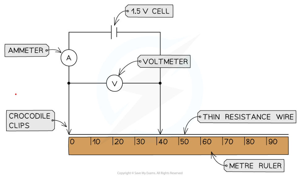
Investigating Resistance
dependant variable = Resistance
independant variable = length of wire
control variable = material of wire
Method:
Set up the apparatus by connecting two crocodile clips to the thin resistance wire a distance of 10 cm apart and setting the power supply to 1.5 V
Connect the wire, using the clips, to the rest of the circuit
Record the potential difference from the voltmeter and current from the ammeter
Using r = v/i calculate resistance
Move the clips in 10 cm intervals further apart and repeat steps 1-4
Take new measurements from the voltmeter and ammeter for each length reading
Continue until the crocodile clips are a length of 1 m apart
Using these results draw a graph of potential difference and current
sources errors in this practical :
Temperature affects resistance, so when the wire heats up, the increased temperature affects the resistance as well as the length of the wire, thus affecting the results. (confounding variable) This could also be a hazard as this could cause burns so :
Only have the circuit connected to take the reading and then disconnect it straight away until you are ready to take the next reading. wait until the wire had cooled back to room temperature before taking the next reading. Use a low potential difference which will keep the current low reducing heating in the wire
zero error
subtract zero error from all readings, change equipment, attach crocodile clip directly onto where the wire is at zero.
IV Characteristics
Ohm's Law states that the current through a conductor is directly proportional to the potential difference across it
Conductors that follow this rule are known as ohmic conductors
Some examples include fixed resistors, wires and heating elements
this can be seen through this graph:

However this is only true if temperature remains constant.
Required practical : Investigating IV characteristic
Set up the circuit as shown with the fixed resistor
Vary the voltage across the component by changing the resistance of the variable resistor, using a wide range of voltages (between 8-10 readings). Check the appropriate voltage reading on the voltmeter
For each voltage, record the value of the current from the ammeter 3 times and calculate the average current
Increase the voltage further in steps of 0.5 V and repeat steps 2 and 3
Make sure to switch off the circuit in between readings to prevent heating of the component and wires
Reverse the terminals of the power supply and take readings for the negative voltage (and therefore negative current)
Replace the fixed resistor with the filament lamp, then the diode, repeating the experiment for each
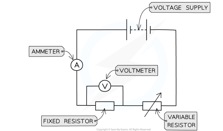
It is easy to change voltage when voltage supply is from a power pack, but if voltage supply is from a cell or battery with a fixed charge one should use a variable resistor to change its voltage
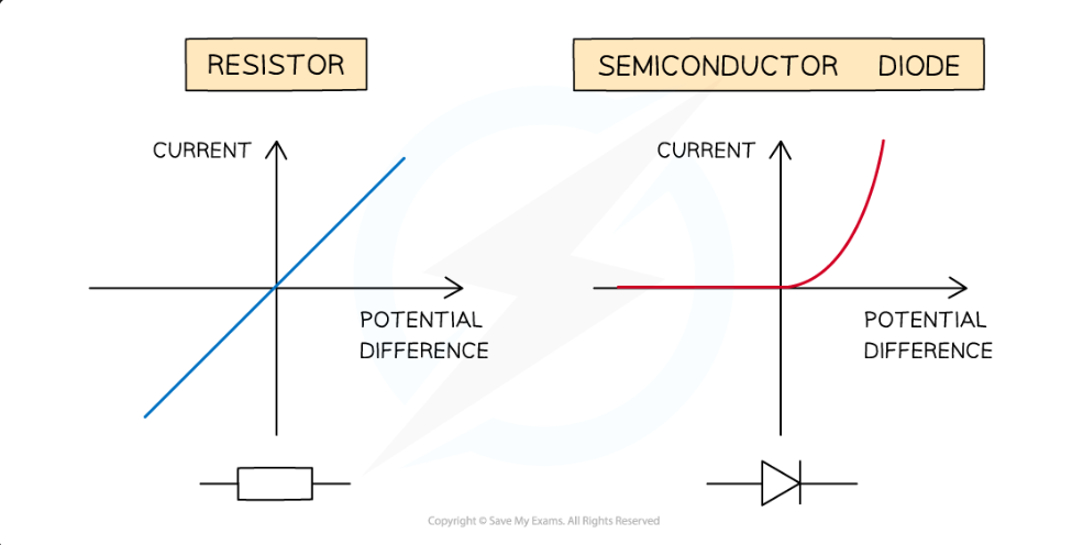
The diode is a semi conductor so it only allows the current to pass through one direction thus has very high resistance in the reverse direction.
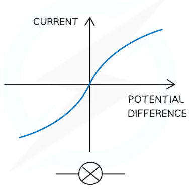
This is because the resistance of the filament lamp increases as the temperature of the filament increases
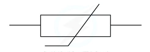
Thermistors and LDRs
A thermistor is a temperature based resistor, meaning its resistance decreases as the temperature increases vice versa.
Thus a thermistor is a temperature sensor and is regularly used as a thermostat which automatically regulates or activates a device when temperature reaches a certain point.
This means it can be used in ovens, refridgerators, fire alarms, digital thermometers and boilers
An LDR is a light-dependant resistor, as the light intensity increases the resistance decreases
An LDR is a light sensor
This means it automatically regulates the amount of light intensity on it or activates a device when the light intensity reaches above or below a certain point
examples include Lights that switch on when it gets dark (eg. garden lights, street lights),Burglar alarm circuits
useful because it is automatic not needing any human time and intervention to function correctly everyday
SERIES AND PARALLEL CIRCUITS
Series and parallel circuits
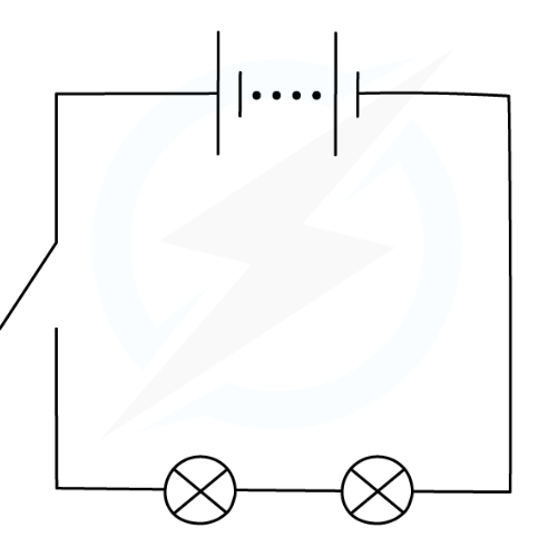
Series
Has no branches so current can only move around in one direction
Current anywhere in the circuit is the same
Voltage is shared between components
the total resistance of two components is the sum of the resistance of each component
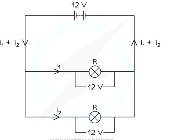
Parallel
Has 2 or more branches so some current moves through both of the branches
the total current through the whole circuit is the sum of the currents through the separate components
The potential difference across each component is the same
The total resistance of two resistors is less than the resistance of the smallest individual resistor.
DOMESTIC USES AND SAFETY
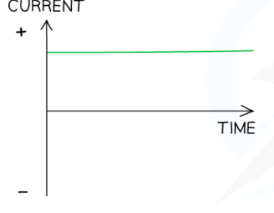
AC AND DC
DC is a current that is steady, constantly flowing in the same direction in a circuit, from positive to negative
DC is usally found in electric cells, or batteries, the potential difference across a cell in a d.c. circuit is in one direction only
A d.c. power supply has a fixed positive terminal and a fixed negative terminal.
AC is a current that continuously changes its direction, going back and forth around a circuit
An a.c. power supply has two identical terminals
Produced by electrical generators i.e mains electricity
Mains Electricity..
In the UK, mains electricity is an alternating current with a frequency of 50 Hz and a potential difference of around 230 V
In the UK, most electrical appliances are connected to the mains using a three-core cable consisting of a live wire, a neutral wire, an Earth wire, which are made up of copper because it is a good conductor but the coating of the wires is made out of plastic because itdoesnt conduct electricity so the wires dont touch.
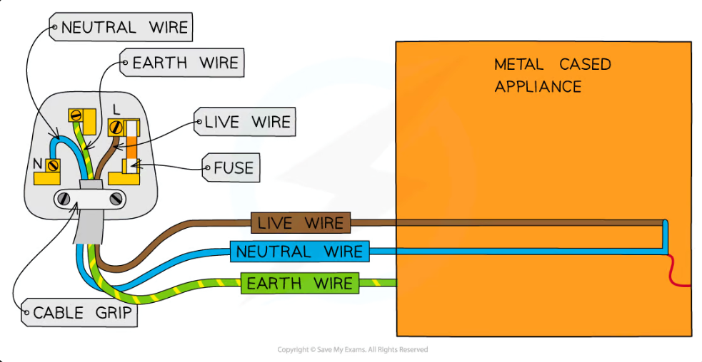
The live wire - brown - Carries the alternating potential difference from the mains supply to a circuit (230v)
It is the most dangerous of the three wires, because evne if the switch is open, the first part of the live wire still has 230V
If it touches the appliance without the Earth wire, it can cause electrocution
The neutral wire - blue - Forms the opposite end of the circuit to the live wire to complete the circuit, Because of its lower voltage, it is much less dangerous than the live wire
The earth wire - green yellow stripes- Acts as a safety wire to stop the appliance from becoming live by providing a low resistance path into the earth, causing a high surge in current causing the fuse to melt and breakthe cicuit
This cuts off the supply of electricity to the appliance, making it safe to touch
This prevents electric shocks from occurring if the appliance malfunctions or the live wire breaks off and touches the case of the plug
Additionally electricians also turn off the mains supply to the house when thwyh are working with live wires because their pot. idff is 0V while the live wire has pott diff of 230 which could cause a current to pass through the person into the earth causing a lethal shock, even if the device is switched off
ENERGY TRANSFERS
Power
BUT power is also dependant on voltage and current represesnted by the equation
P (W) = I (A) x V (V).
Due to the fact that resistance also affects voltage, the equation V= IR can be rearranged to become P (W) = I² (A) x R (Ω)
Energy Transfers
The amount of energy transferred to and from an appliance depends on:
The time the appliance is switched on for
The power of the appliance
This can be represented by the equation E (J) = P(W) x T (s)
Additionally potential difference and charge are also factors affecting energy, represented by the equation E (J) = Q (C) x V (V)
Power Ratings
Every electrical appliance has a power rating which tells you how much energy it needs to work
The power rating for domestic electrical appliances is normally given on a label. This will include:
The potential difference required to make the device work (eg. 230 V in the UK)
The frequency of the supply (eg. 50 Hz in the UK)
The power rating in Watts (this varies for each device)
The higher the power rating, the faster the energy is transferred
National grid
System of cables and transformers linking power stations to consumers (houses, factories and buildings)
a main problem of transferring energy over long distances is that it is lost very easly this is why transformers have to be used
Step up transformers are used to increase voltage because less energy is lost when there is a higher voltage
however the voltage is too high so a step down transformer is used to lower voltage to 230 v so it can be passed into homes safely
Static Electricity
This is the electricity caused by the movement of charge in a circuit in conductors
one example of this is a balloon and a wall:
1) Rubbing a balloon on a woollen jumper transfers electrons onto the balloon by friction
2) The balloon becomes negatively charged and the jumper becomes positively charged
3) The wall is uncharged initially, but when the balloon is placed near the wall, the electrons on the balloon's surface repel the electrons on the wall's surface
4) Furthermore, the positive charges on the wall's surface are attracted to the negatively charged balloon which allows the it to stick to the wall
Sparking
A spark occurs between two objects when
There is a large potential difference between the two objects
Which causes a current to flow between them
Caused by a build up of charge
Electrical Fields
A charged object creates an electric field around itself
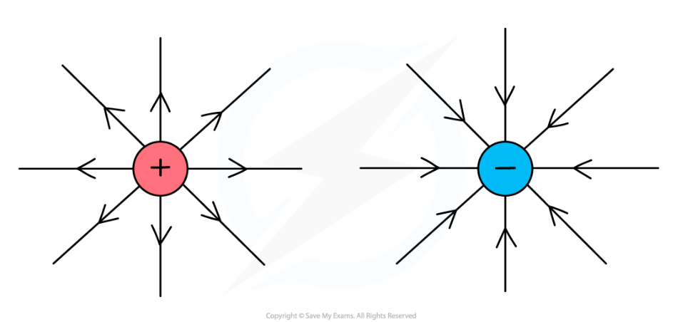
the force becomes:
Stronger as the distance between the two charged objects decreases