Transformer Fundamentals Video Notes - Fill-in-the-Blank Flashcards
Transformer Construction, Operation, and Safety – Study Notes
Overview
Transformers transform high voltage from power lines to lower voltages suitable for home use.
They are essential in modern life; raw power is not usable to consumers without proper stepping down.
Commonly seen on utility poles and in substations; many components are encapsulated in a steel tank with oil for cooling/insulation.
Construction: starting materials and assembly sequence
Core components and initial winding materials
Paper wrapped in epoxy glue to insulate windings; wrapped around a rotating block to form coils.
An eighth-of-an-inch thick aluminum strip is used as a low-voltage lead (aluminum = low voltage lead in this context).
Copper wires are used for high-voltage windings.
Winding and layering process
The block is rotated; paper and aluminum strips are wrapped around to form the windings.
Epoxy glue on insulating paper bonds layers when heated in later steps.
A high-voltage lead wire is soldered to the copper winding, and another layer of copper winding is added.
A copper lead wire emerges from the winding (the lead wire out) and connects to external bushings.
Coil and core assembly
The completed unit is called the coil (the high-voltage coil plus low-voltage coils).
The transformer’s core is built from electrical steel; the coil(s) and core are then wrapped and secured with metal strapping.
The whole assembly is then pressed/fixed together in a tank and sealed.
Curing and bonding
The assembly is placed in an oven and baked for eight hours at 275°F to remove humidity and fuse the layers of paper, aluminum, and copper with the glue.
Tank, bushings, and initial electrical interfaces
The coil assembly is placed into a steel tank; a rubber gasket is installed around the perimeter; a grounding wire is bolted on.
Three thermoplastic bushings are inserted; low-voltage leads connect through the bushings to the tank.
An oil-filling guide is attached, and the tank is filled with mineral oil; a vacuum is drawn to aid dispersal of oil through the coil and core.
Additional components and testing interfaces
An internal fault detector monitors for short circuits.
The transformer has a lead wire out and insulated, vinyl-coated wire connections for external voltages.
A ground strap connects to the tank for safety; a lightning surge arrestor (surge arrestor) is connected to divert surges to ground.
The unit is topped by a cover; after testing, wiring, and sealing, the transformer is ready for service.
Core concepts: coil vs core and how a transformer works
Coils and core
The coil(s) are winding(s) that carry current; the core is the magnetic circuit made of electrical steel.
Do not confuse the coil with the core; they are different components but work together.
Operation principle
Transformers operate on induction with no moving parts inside.
The turns ratio determines whether the transformer steps voltage up or down.
Increasing turns on the secondary relative to the primary yields a step-up; decreasing yields a step-down.
Turns ratio basics
Turns ratio is the relation of windings: rac{Vp}{Vs} = rac{Np}{Ns} where Vp and Vs are the primary and secondary voltages, and Np and Ns are the number of turns on the primary and secondary.
If you use only one leg of the secondary for a measurement, the ratio is ext{Turns ratio} = rac{Vp}{V{s, ext{leg}}}.
Practical voltages and step up vs step down (examples)
Outside a house: typically step down from distribution voltages to lower service voltages (e.g., 7,200 V to 120/240 V)
At the substation: sometimes step up for transmission purposes (e.g., to higher transmission voltages)
Example turns scenarios
If you have 120 V on the primary and a secondary with 240 V, the turns ratio appears as 1:2 in the simple illustration, depending on how you count turns.
If you have 7,200 V input and 120 V output on one leg of the secondary, the ratio is rac{7200}{120} = 60:1 ext{ (one leg of secondary)}. The overall secondary to primary ratio using 240 V across the two hot legs is different (e.g., 7200:240 = 30:1).
Common case: 7200 V to 120/240 V is a 60:1 ratio per hot leg (primary to each hot leg on the secondary).
Turns and labeling: X, H, and polarity concepts
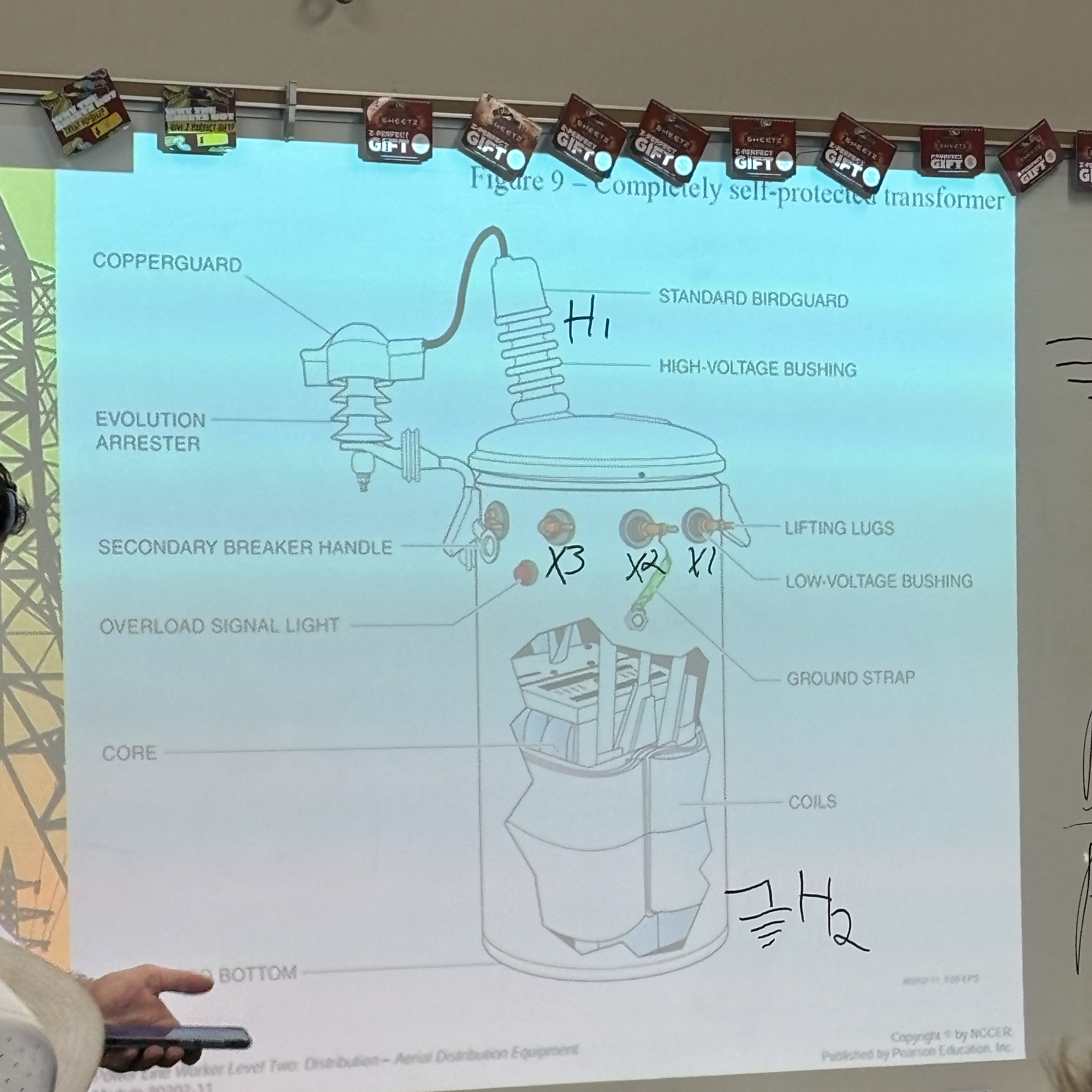
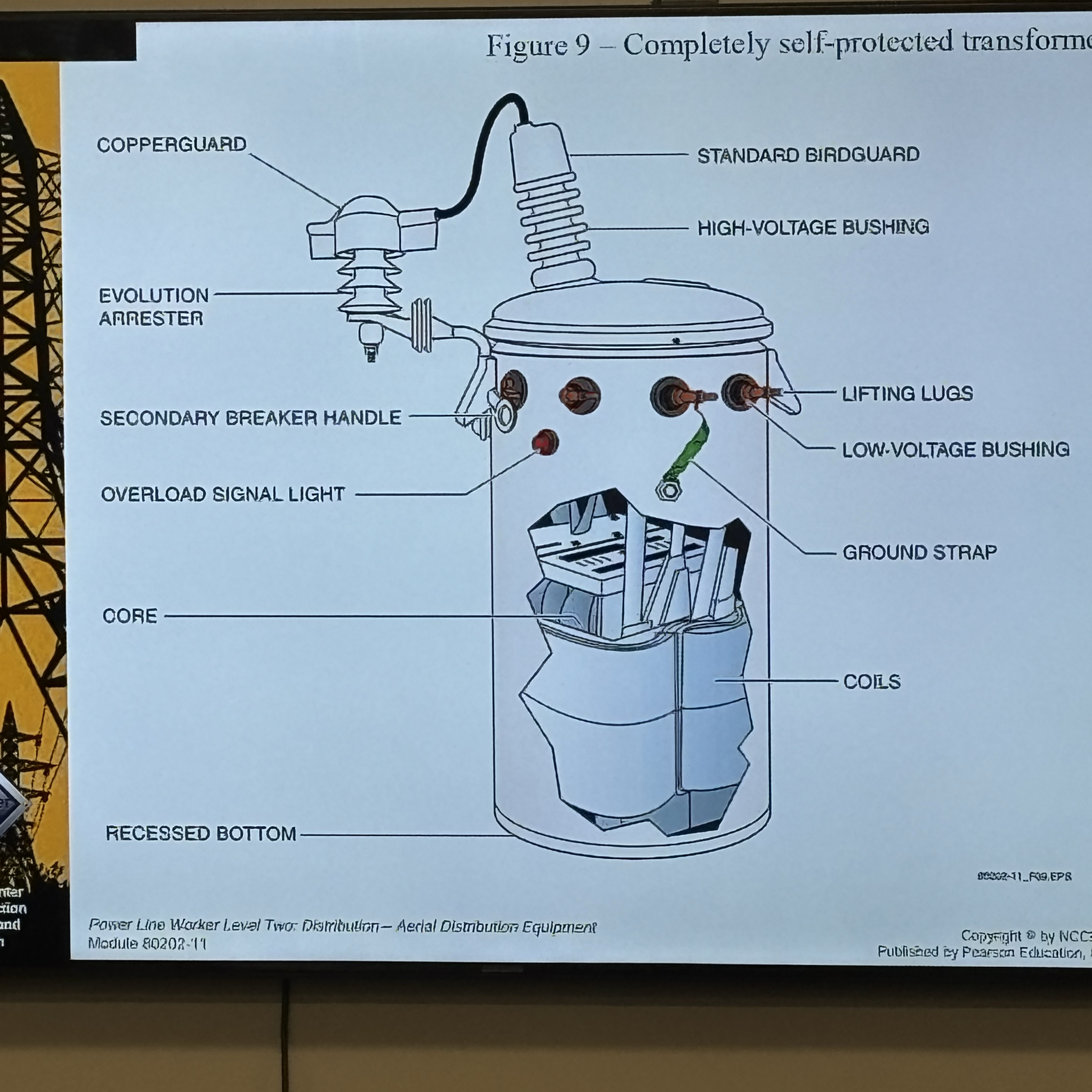
Secondary windings labeling: X1, X2, X3 are the secondary bushings; H1 and H2 are the primary bushings.
Ground/neutral relationships
The neutral is typically tied to a center point in the winding and is expected to be at 0 V with respect to ground.
The copper grounding strap is connected to neutral, not to a live conductor.
A ground symbol on the schematic identifies the ground path; be mindful that tying neutral to a live conductor (e.g., 120 V) would be dangerous.
Neutral voltage checks
Neutral should read 0 V relative to ground; connecting ground to a live conductor would be dangerous and produce hazardous conditions.
Polarity and bushing naming conventions
Secondary bushings have names such as X1, X2, X3 (left-to-right convention in the image can be additive or subtractive depending on orientation).
Additive vs subtractive polarity
Reading left-to-right as X1, X2, X3 yields subtractive polarity (the opposite of additive). Reading right-to-left yields additive polarity.
Common field practice
In yard installations, additive transformers are more common; subtractive polarity is less common except in underground or large overhead configurations.
Ground and case ground
H2 is often the case ground on the secondary side; pay attention to the labeling and avoid confusing the surge arrestor with a bushing.
Lightning and surge protection
Surge arrestors are protective devices used to shunt lightning surges to ground, protecting the transformer and line.
They are connected via a copper strap and grounded; the arrestor provides a path to ground for surges.
The exact term is often “surge arrestor” rather than “evolution arrestor.”
Lifting, mounting, and field handling
Transformers have lifted lugs for safe handling; many can be moved in place with two people using slings or special hardware.
If a transformer does not have lifting lugs on both sides, other methods are used (e.g., a sling, “canning” the pole with a pole-borer tool, or using a block-and-tackle).
When transporting and installing, plan for space and mounting constraints (spacing of multiple transformers on a pole, etc.).
Extendo stick (hot-sticking) and hurt-man rescue
Extendo stick allows remote disconnection or control from the ground; it is a field-critical tool for isolating or turning off a transformer from below.
Hurt-man rescue training emphasizes working with this tool; correct use requires practice.
Switches, fuses, and protection logic
Fuses and cutouts
Fuse cutouts provide overcurrent protection on the transformer’s secondary circuit. When a fault occurs, the fuse opens, isolating the transformer from the line.
The CSP (Completely Protected) handle is a red handle that, when operated, kills the secondary side power to that transformer.
CSP and safety logic
The CSP handle shuts off power to the secondary side, allowing maintenance without energizing the transformer.
Breakers and automatic trips
Secondary overload can trigger a breaker to trip automatically, isolating the transformer to protect the system.
Backfeed risks (generator backfeed)
If a generator is connected incorrectly, power can be fed backward into the transformer, potentially energizing the top of the transformer and posing a lethal risk to line workers.
Proper method: use a transfer switch to isolate from the grid; do not rely on “suicide cords” or direct connections to the house outlets.
Generator safety and isolation measures
Install a transfer switch to stop backfeeding; if not possible, temporarily disconnect the meter to isolate the home from the grid.
If a generator is running, workers must locate it and avoid touching live conductors; listen for a generator’s distinctive sound and use the meter pull method to disconnect when necessary.
Backfeed, generation, and safe practice scenarios
Backfeeding dangers
A generator feeding 7,200 V into a transformer’s bottom side can transfer higher voltage to the top side, creating a dangerous condition for line workers.
Even when the grid is out, a backfed transformer can energize lines and cause electrocution hazards.
Safety practice and communication
If you hear a generator in the area during a storm, communicate with the customer to disable or isolate the generator before work begins.
Use a proper transfer switch and avoid improvised connections.
Isolation, testing, and grounding as a habit
Isolate, test, and ground
Do not assume a line is dead; isolate the section you will work on, test it, and then ground it as a safety precaution.
Meter and seals awareness
Power meters on houses can act as seals; tampering with seals is dangerous and often illegal; severing meter seals can incur penalties and should be avoided.
Training emphasis
The class emphasizes hands-on practice with isolating and testing live lines, including practice with the extendo stick and other safe procedures.
Oil, insulation, and PCB hazards
Transformer oil and PCBs
Old transformers used mineral oil; before 1979, polychlorinated biphenyls (PCBs) were used in some transformers; PCBs are carcinogenic and persistent in the environment.
Identification and handling
If a transformer oil appears questionable or rusted, tests can determine PCB presence.
Blue dot tests indicate PCB status; CSI kits can change color to reveal the type of oil.
Cleanup and soil remediation
If PCB-contaminated soil is suspected, the soil must be removed and replaced with clean fill; contaminated soil must be disposed of according to regulations.
Health and safety implications
PCB exposure can be acute (immediate harm from fumes) or chronic (carcinogenic over time).
Oil properties and transformer performance
Mineral oil properties
Mineral oil provides cooling and insulation; it helps carry heat away from windings.
Oil vs PCBs
PCBs have been largely phased out in modern equipment due to health risks; most transformers now use mineral oil or other safer fluids.
Monitoring, testing, and fault detection
Internal fault detectors
Transformers include detectors that alert maintenance if a short occurs inside the transformer.
Leak testing and oil level checks
If oil levels are low, the transformer could be leaking; the unit should be swapped for a replacement rather than repaired in place.
Ratings: kVA, voltage, and how capacity affects design
What is kVA?
Kilovolt-amperes (kVA) is the size or rating of the transformer, representing how much apparent power it can handle.
The energy you can draw from a transformer depends on its kVA rating, not just its voltage.
Voltage and current relationship
A transformer’s output voltage is determined by the turns ratio; the current capability is tied to the kVA rating and voltage.
Why not always use a very large transformer?
Larger kVA ratings cost more up front and have higher internal losses (even with high efficiency). As efficiency rises, losses per kVA decrease, but absolute loss can still be higher for larger units.
Practical sizing examples
A 25 kVA transformer can support several homes; a 100 kVA transformer can supply more but is more expensive, heavier, and has higher insulation demands.
Efficiency
Typical transformer efficiency is around 98.5 ext{%}, implying roughly 1.5 ext{%} losses at full load.
Weight, mounting, and pole infrastructure
Weight is critical for safety and pole load calculations; you must know the weight to select appropriate lifting gear and to comply with OSHA requirements.
Pole mounting for multiple transformers requires considerations for space, canning, and can configurations (three cans or more on a rack for larger installations).
Safety, training, and practical field advice
Grounding and fencing
Proper grounding (case ground) and isolation are essential to minimize shock hazards.
Hurt-man rescue and training emphasis
Proper training in safe handling, including the use of extendo sticks for turning off transformers from the ground, is emphasized.
Real-world experience and test prep
The instructor emphasizes practical knowledge and field-tested procedures; the material is designed to prepare for tests that include identifying components and understanding transformer operation.
Common components and terminology recap
H1 and H2 bushings (primary connections)
X1, X2, X3 bushings (secondary connections)
Ground symbol and case ground (H2 often serves as case ground in many installations)
Lightning/surge arrestor (surge arrestor)
Lift lugs and lifting hardware; camper/slings; block-and-tackle for installation
Extendo stick (hot-stick) for remote operation
Fuse cutouts and the CSP (Completely Protected) handle
Wild-left guard (protective clamp that acts as a barrier to protect the tank from the line and worker during operations)
Backfeeding concepts and transfer switches
CSI oil tests and blue-dot PCB status indicators
KVA rating, voltage levels, and corresponding loading considerations
Quick reference formulas and concepts (for exam prep)
Voltage transformation (ideal transformer): rac{Vp}{Vs} = rac{Np}{Ns}
Turns ratio using a single leg of the secondary: ext{Turns ratio} = rac{Vp}{V{s, ext{leg}}}
Fuse sizing approximation (single-phase path): I_ ext{fuse} ext{ (A)}
oughly rac{ ext{kVA}}{V_p}Example: For a system with Vp = 7200\ ext{V} and measuring one leg of the secondary as V{s, ext{leg}} = 120\ ext{V}, turns ratio ≈ rac{7200}{120} = 60:1
Efficiency and losses: typical efficiency ≈ 98.5\%; loss ≈ 1.5\% of rated power (varies with size and load)
Neutral and ground safety: neutral should be at 0 V with respect to ground; misconnecting can be dangerous; never tie neutral to a live hot leg.
Ethical and practical implications
Handling PCB-containing equipment or previously PCB-filled oil requires strict environmental and health safeguards; improper handling risks long-term health and environmental harm.
Safety is the top priority when working with high-voltage equipment; proper isolation, testing, and grounding reduce the risk of electrocution to workers and the public.
Accurate labeling (nameplates, additive/subtractive polarity, and kVA ratings) is essential for safe operation, maintenance, and compatibility with the electric grid.
Connections to foundational principles and real-world relevance
Transformers are a direct application of electromagnetic induction and the principle of energy conservation (minus losses).
Understanding turns, voltage relationships, and load capacity is essential for designing, installing, and maintaining power distribution networks.
Practical field practices (isolate/test/ground, use proper tools, and follow transfer-switch protocols) are critical for worker safety and system reliability.
Examples and scenarios highlighted in the transcript
Building a transformer coil: layered winding around a rotating block with insulating paper, epoxy glue, aluminum low-voltage strip, and copper windings.
Determining whether a transformer is additive or subtractive using the X1–X3 labeling and the left-to-right reading convention.
Calculating turns ratio in a real-world setup (7200 V primary, 120 V single leg secondary) to establish a 60:1 ratio.
Understanding backfeed danger when a generator is improperly connected and the role of a transfer switch.
Differentiating surge arrestor vs. expansion or “evolution” terminology and why the correct term is surge arrestor.
PCB oil detection methods (blue dot tests and CSI color tests) and environmental remediation steps when PCB contamination is detected.
Summary takeaway
Transformers are robust, mostly passive devices whose effectiveness relies on correct winding configuration, proper insulation, accurate labeling, safe handling, and rigorous safety protocols. Understanding the turns ratio, labeling (X1, X2, X3, H1, H2), oil types, and protection features (fuse cutouts, CSP, surge arrestors) is essential for safe operation in the field and for success on assessments that test knowledge of transformer components and their function
Construction Details (Coil Winding)
Paper wrapped in epoxy glue to insulate windings around a rotating block.
An eighth-of-an-inch thick aluminum strip used for low-voltage leads.
Copper wires used for high-voltage windings.
The block rotates, wrapping paper and aluminum/copper strips to form windings.
A high-voltage lead wire is soldered to the copper, and a copper lead wire emerges for external connections.
Coil and Core Assembly
The completed unit, called the coil (high-voltage plus low-voltage coils).
The transformer’s core is built from electrical steel.
Coil(s) and core are wrapped and secured with metal strapping.
The whole assembly is pressed/fixed together in a tank and sealed.
Tank, Bushings, and Oil-Filling
Coil assembly placed into a steel tank with a rubber gasket.
A grounding wire bolted on.
Three thermoplastic bushings with low-voltage leads connected through them to the tank.
An oil-filling guide is attached, and the tank is filled with mineral oil.
External Components and Safety Devices
Lead wire out and insulated, vinyl-coated wire connections for external voltages.
A ground strap connected to the tank.
A lightning surge arrestor connected to divert surges to ground.
The unit topped by a cover.
Field Installation and Safety Tools
Lift lugs on transformers for safe handling.
Extendo stick for remote disconnection/control from the ground.
Fuse cutouts for overcurrent protection on the secondary circuit.
CSP (Completely Protected) handle (red handle) to kill secondary side power.
Power meters acting as seals on houses.
Transformer Polarity and Bushings
Secondary bushings labeled X1, X2, X3 (left-to-right convention).
Primary bushings labeled H1 and H2.
Ground symbol on schematic identifying the ground path; neutral typically at 0 V to ground.
PCB Testing
Blue dot tests to indicate PCB status.
CSI kits that change color to reveal the type of oil.
formers
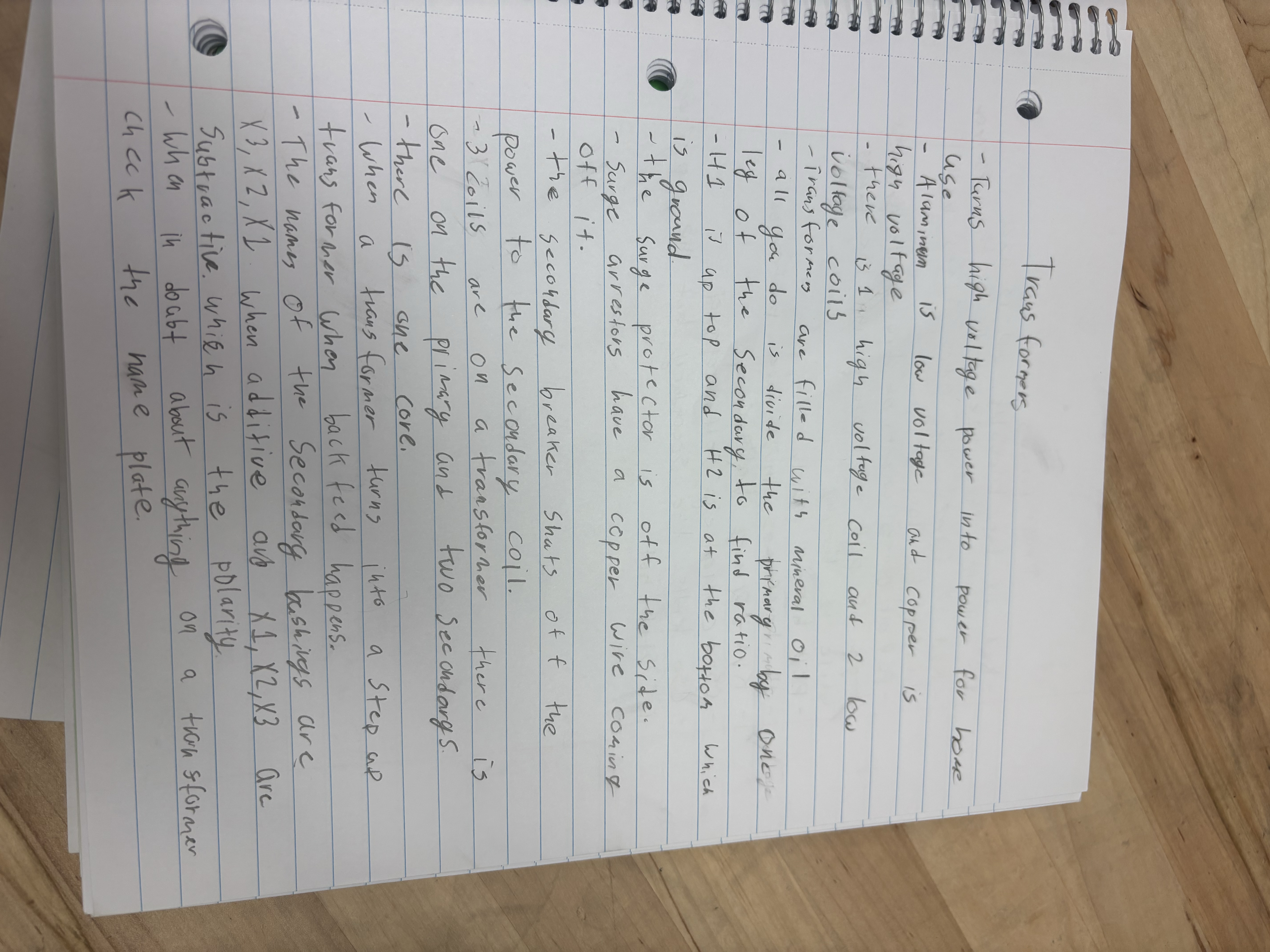
- Turns high voltage power into power for home
use
Alaminen is low voltage
and Copper 15
hign voltage
there is 1 high voltage coil and 2 low voltage coils
Transformer are filled with mineral oil
all you do is divide the primary by one ley of the Secondary, to find ratio.
11 it ap top and H2 is at the bottom which
15 ground
the surge protector 1s off the Side.
Surge arrestors haue a copper wire coming off it.
the secondary breaker shats off the Dower to the Secondary coil.
3 oils are on a transformer there is one on the primary and two Secondongs.
there is one core.
When a trans former turns into a Step as trans former when back feed happens.
The names of the secondary bashings are x3, x2, X1 when additive avo X1, X2,X3 Are Subtractive. whieh is the polarity
When in doubt about anything on a transformer check the name plate
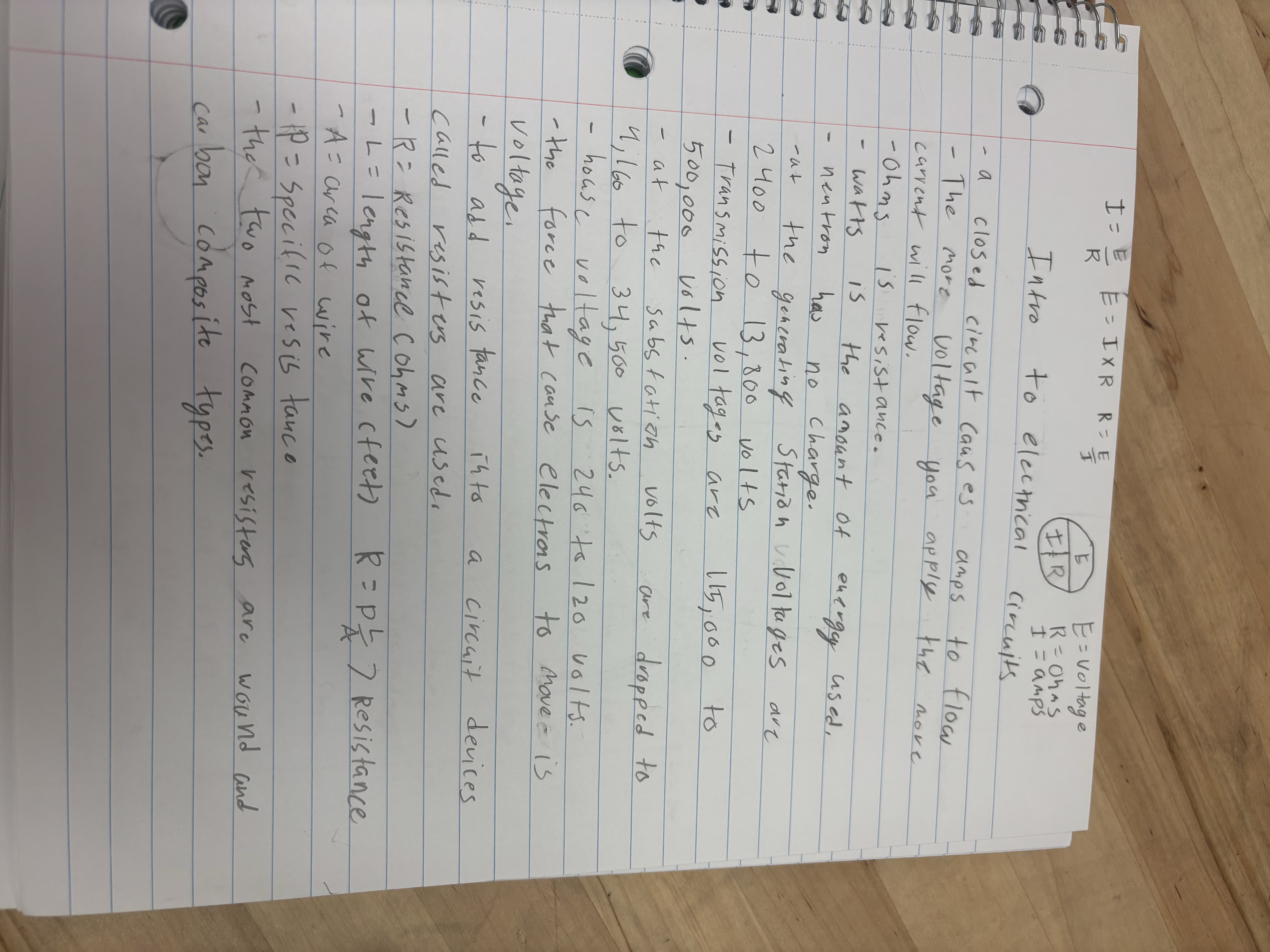
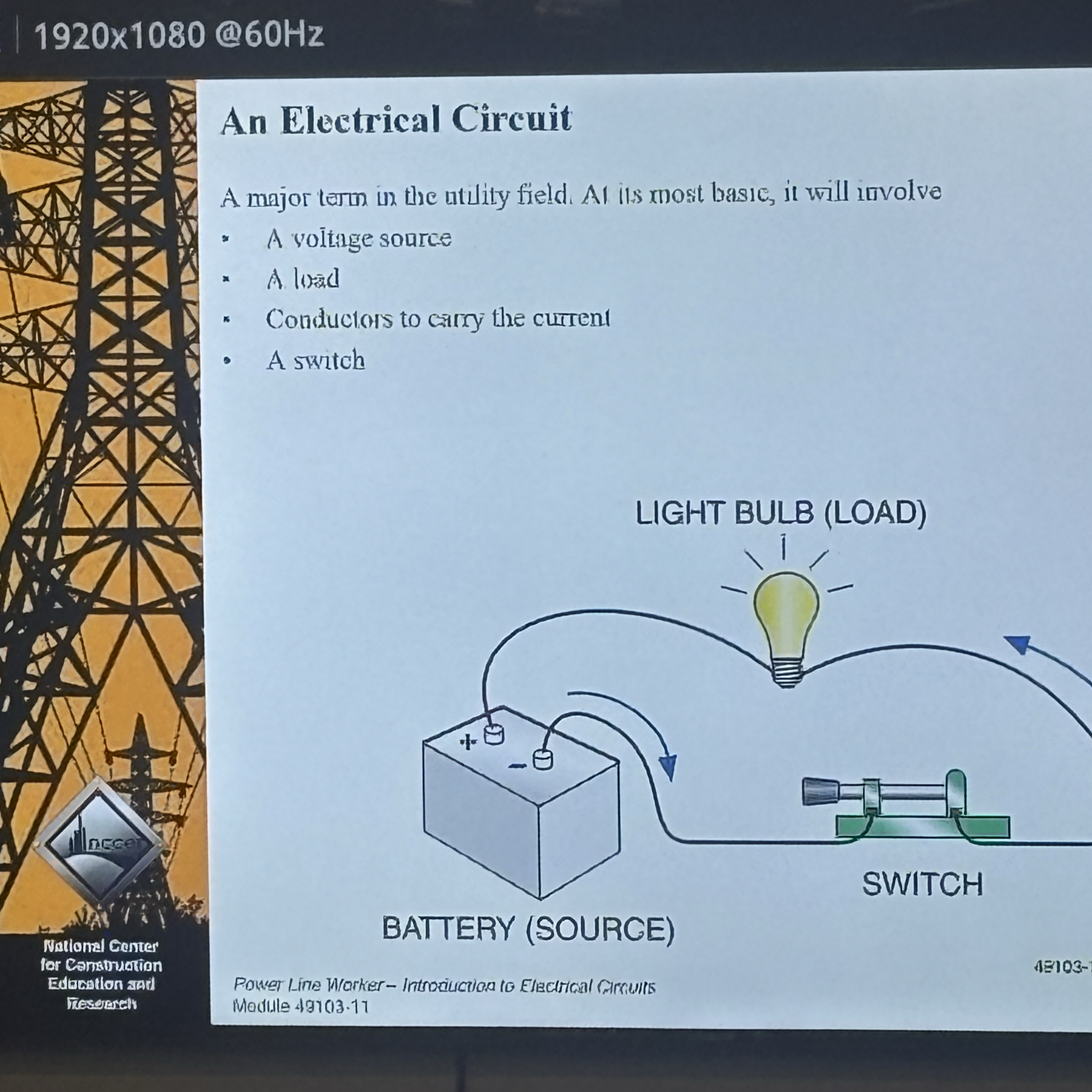
a closed circalt causes amps
to flow
- The more voltage you apply
the nove
carrent will flow.
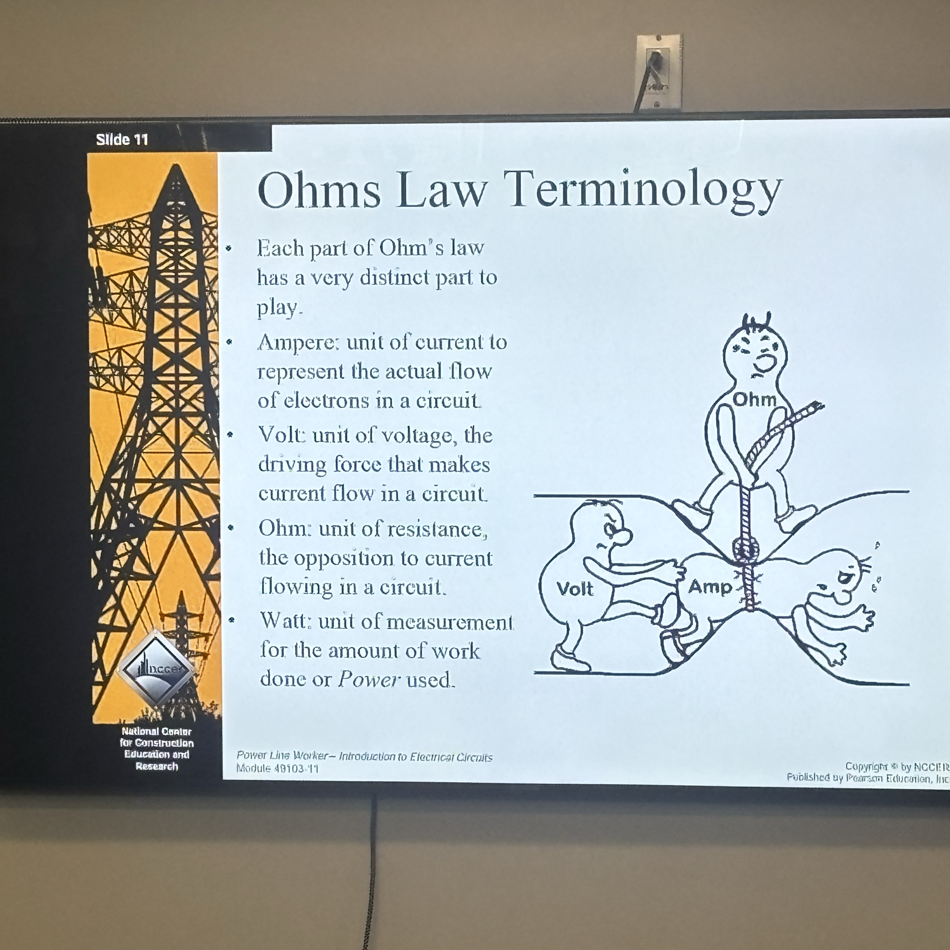
Ohms is resistance.
watts is the amount of energy used.
neutron has no charge.
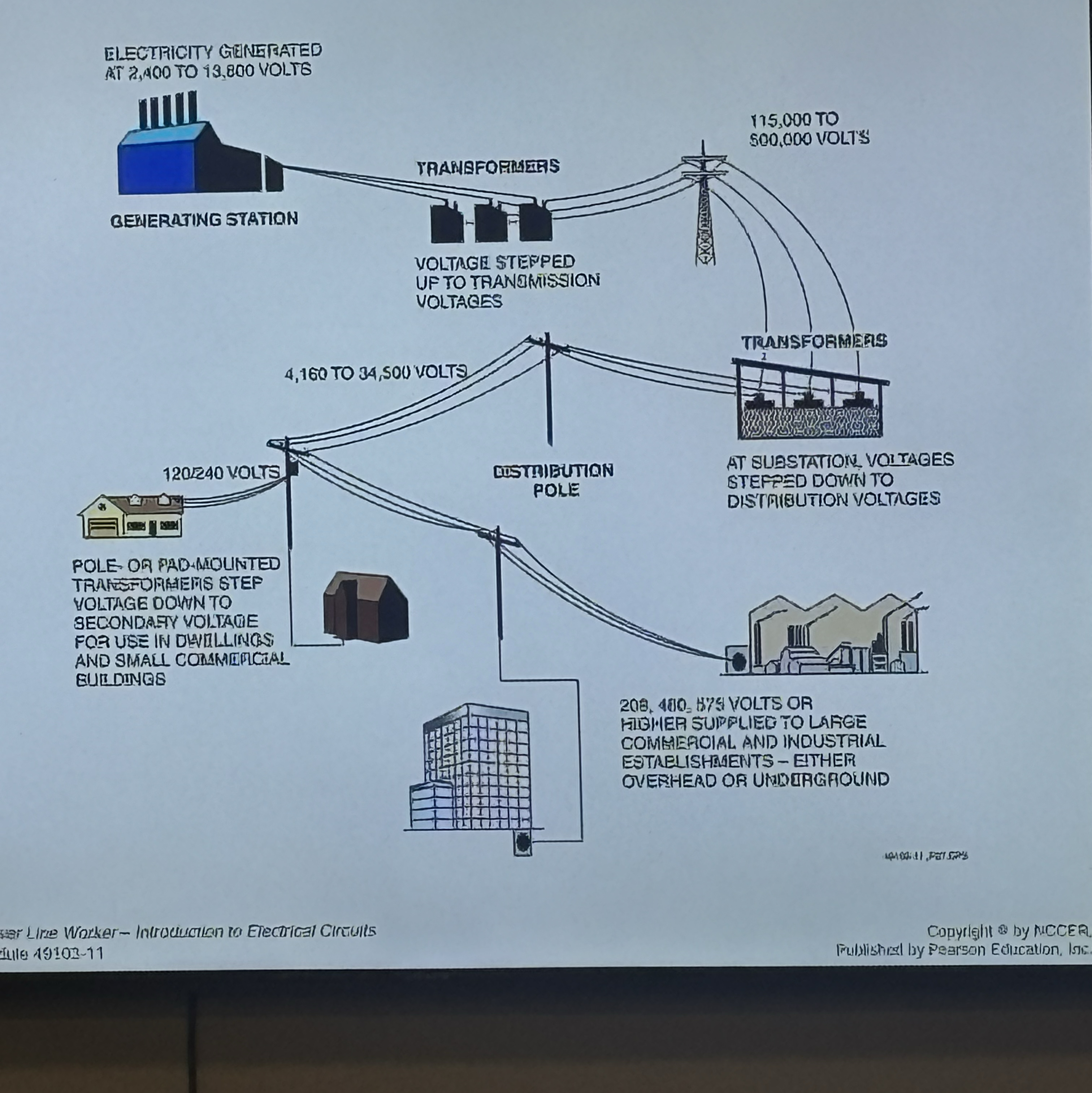
at the generating Station Voltages are 2400 to 13,800 volts
Transmission voltages ave
15, 000 to
500,000 Volt5.
at the sabstatich volts are dropped to 4, 160 to 34,500 volts.
house voltage is 248 ts120 volts.
the force that cause electros to move is
voltage:
- to add resistance
into a circuit devices
called resisters are used
- R = Resistance Cohms)
- L= length ot Wive (fert) R=P/ > Resistance
- A= area of wire
AP= specific resis tanco
The two most common resisters are wound and carbon composite types.
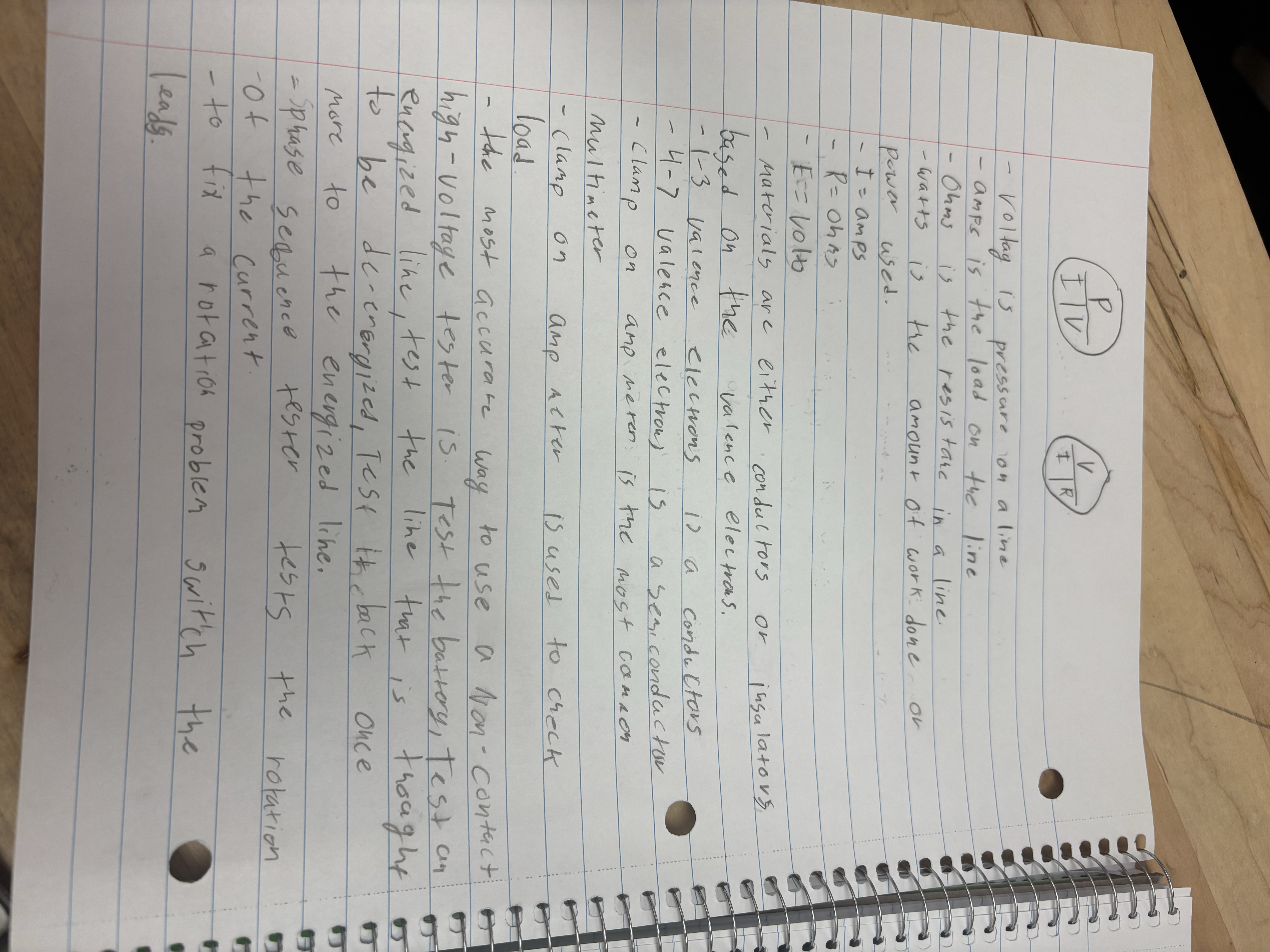
Voltag is pressure on a line
amps is the load on the line
Ohms is the resistare in a line.
watts is the amount of work done. or power used.
I=amPs
R= OhRs
E== volo
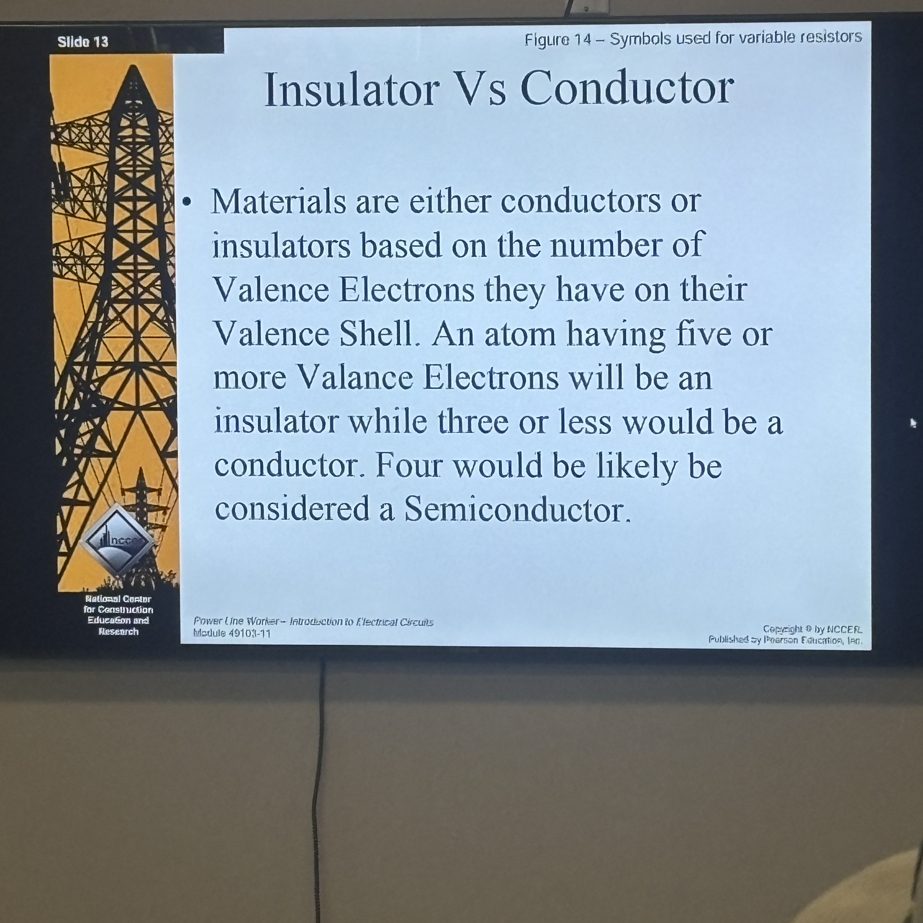
materials are either conductors or ingalatovs based on the valence electras.
1-3 varence electrons is a conductors
4-7 valence electroni is a semicondactor
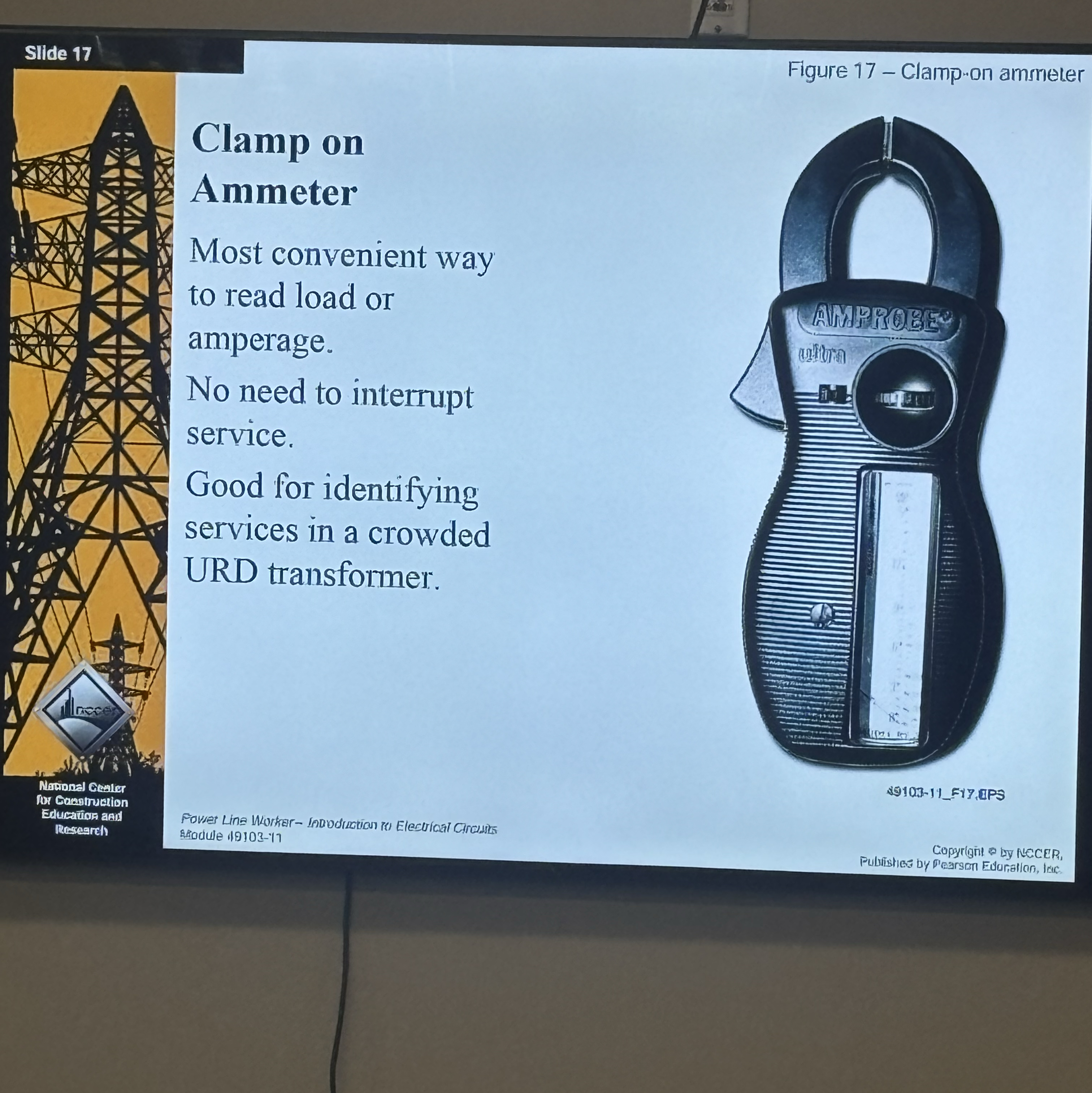
Clamp on amp meren is the most cannon multimeter
clamp on amp meter
is used to check
load
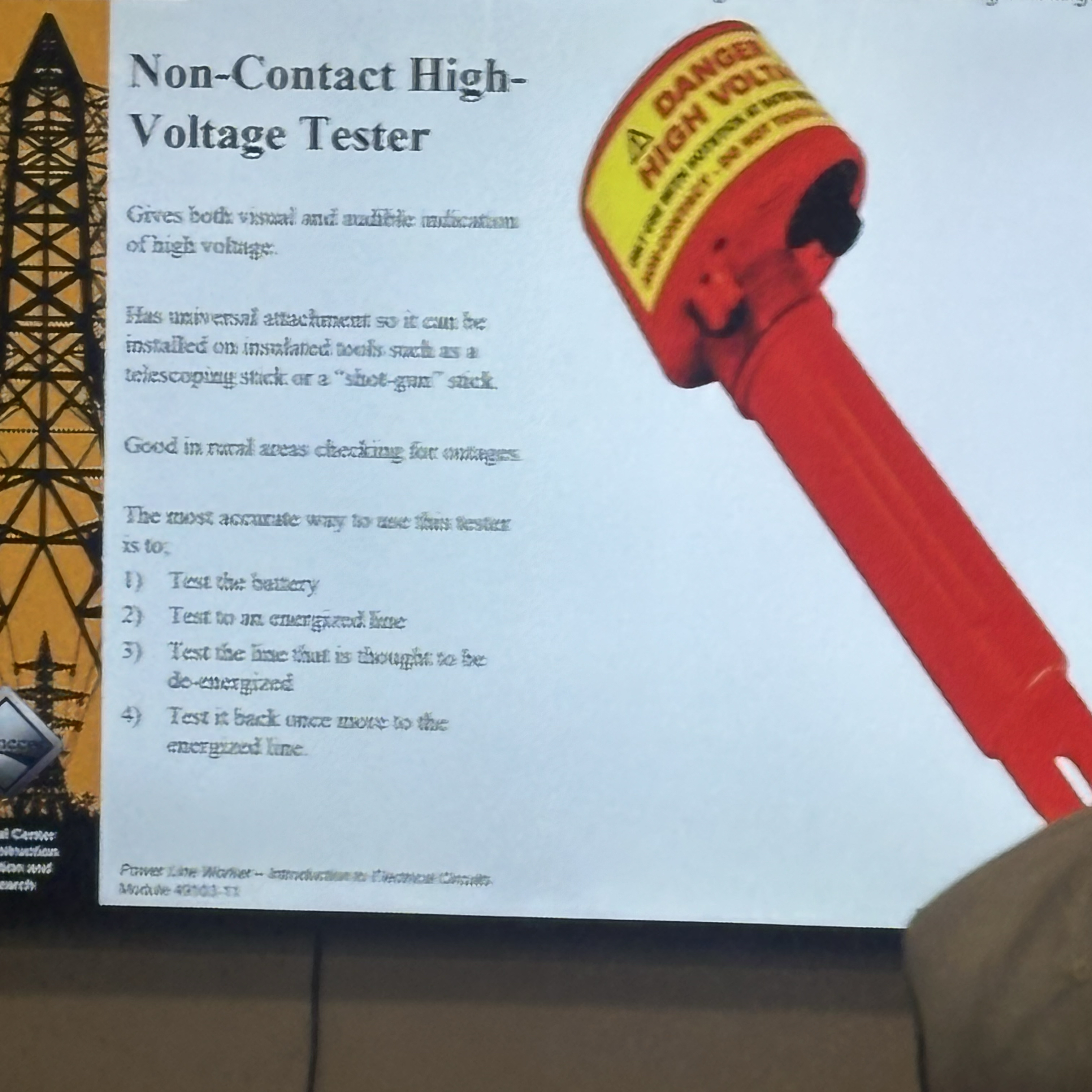
high- voltage tester is. Test the battery, Test an enogized lime, test the like that is thought to be de-energized, Test theback once more to the energized line.
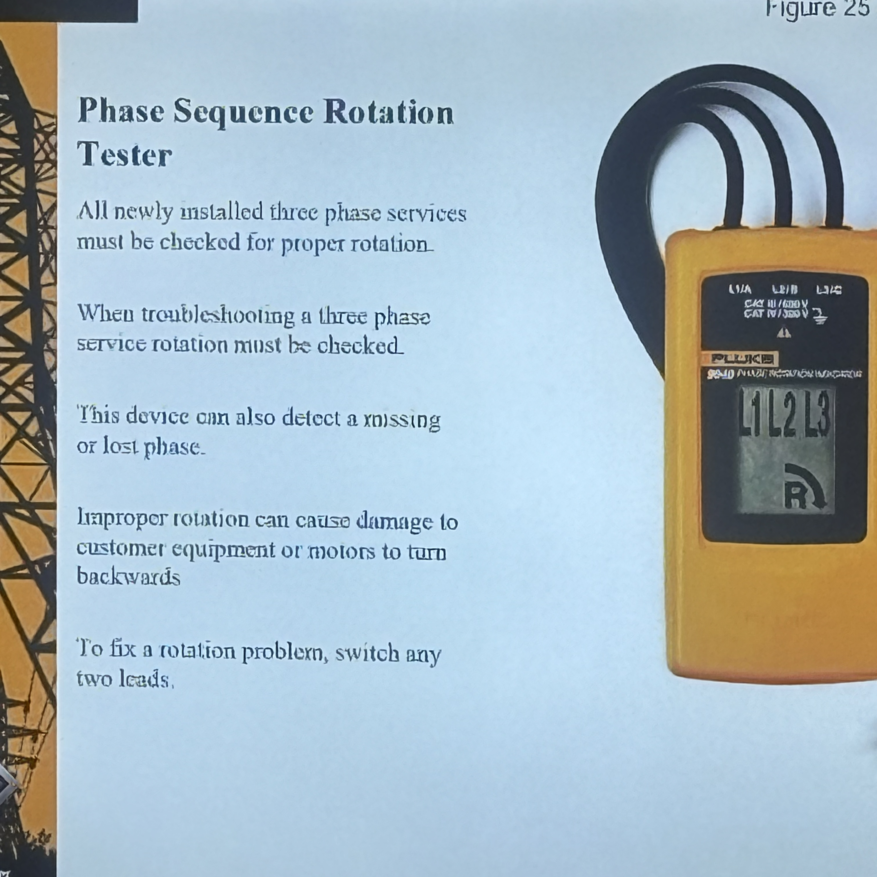
phase seguence tester tests the rotation
Ot the current.
to fix a notation problem switch
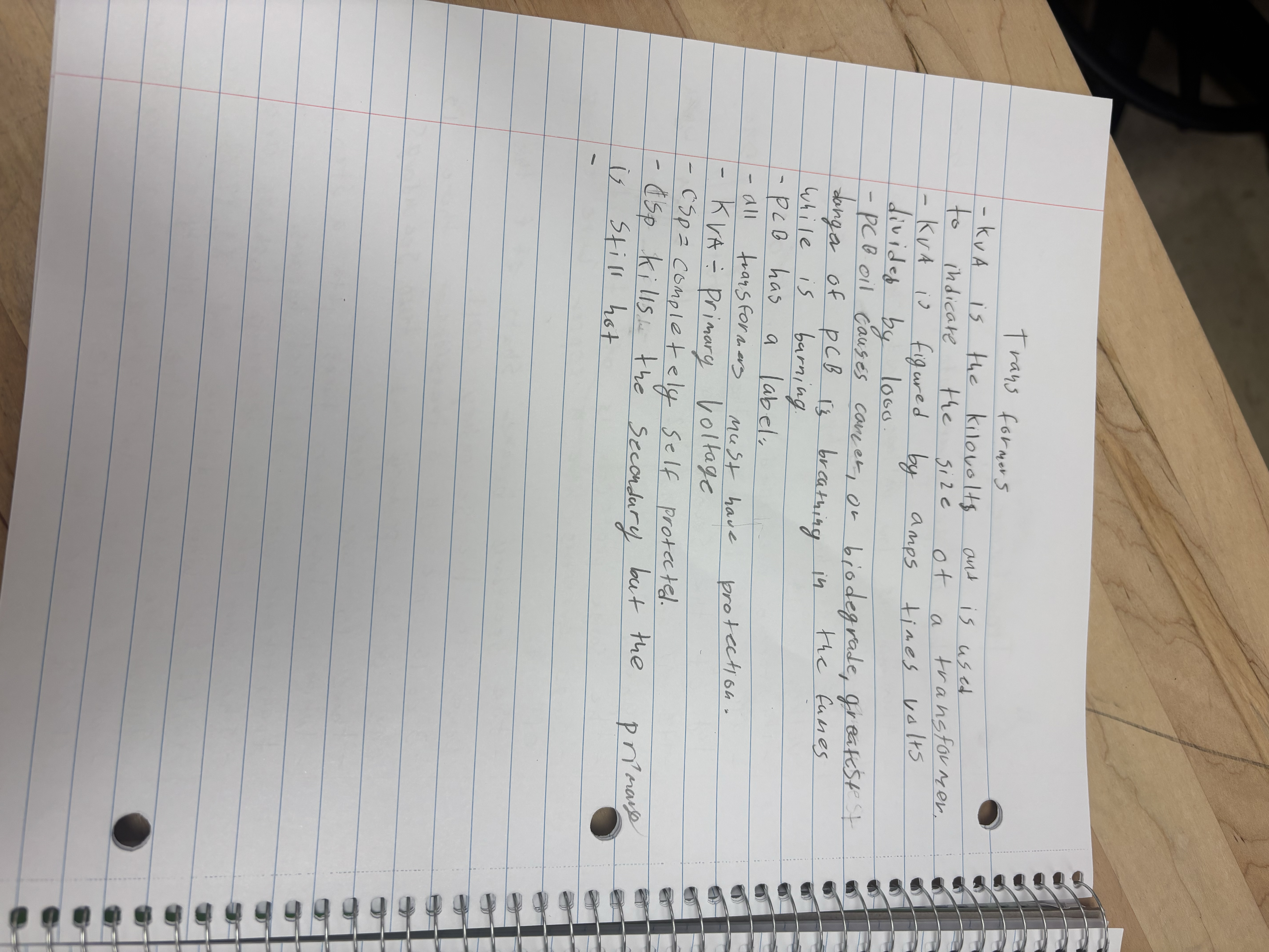
KVA is the Kilovolts ant is used to indicate the size of a transformer.
KVA i figured by amps times valts iridol Causes concer, or biodegrade, greatest t danga of PCB is breathing in the fumes while is barning.
PCB has a label:
all transformers
Must have protection.
- KVA = Primary Voltage
1- Cop= completely Self protected.
- Esp Kills the secondary but the primars
31
1
Still hot