Driven Right Leg Circuitry Note
🎯 Purpose of DRL Circuitry in ECG Systems
The Driven Right Leg (DRL) circuit is used to:
Reduce common-mode interference, especially from power line noise (50/60 Hz),
Stabilize the body’s average voltage, and
Protect the patient from any abnormal voltages between the body and the system.
It does this by using an active feedback system that senses noise, inverts it, and feeds it back into the patient’s right leg — cancelling it out.
1. Why it’s needed
In a basic ECG setup:
Two measurement electrodes (say, RA and LA) connect to an instrumentation amplifier (IA).
The IA is designed to:
Amplify the difference in voltage between its inputs (the differential-mode signal — your ECG).
Reject signals that are common to both inputs (the common-mode voltage — usually unwanted noise).
So far, so good.
⚠ 2. The IA Has Limited Ability to Reject Common-Mode Voltage
The IA does not remove all of the common-mode signal — it only suppresses it to the extent that its hardware allows.
This suppression is measured by a spec called CMRR (Common Mode Rejection Ratio), defined as:
A typical CMRR might be 80–100 dB, which means it suppresses common-mode voltage by a factor of 10,000 to 100,000.
Sounds huge — but remember:
The common-mode voltage can be very large (e.g. 1–2 volts of 50 Hz noise).
The ECG signal is very small (0.5–5 mV).
So even a tiny leak-through of the common-mode signal can dwarf the ECG signal.
🔄 3. Why Add the Right Leg Circuit?
Because the IA can't perfectly remove common-mode noise, we add the Driven Right Leg (DRL) circuit to actively reduce the common-mode voltage at the source — on the patient's body.
What does DRL do?
It measures the common-mode voltage — typically using two averaging resistors from the IA inputs (RA and LA).
Then it inverts that common-mode signal using an op-amp.
The inverted signal is fed back into the body via the right leg electrode.
This feedback acts like active noise cancellation: the injected signal cancels out the original common-mode disturbance.
📉 4. How Much Common-Mode Is Cancelled by the DRL?
Substantial reduction — in many cases, the DRL can reduce the common-mode voltage by an additional 20–40 dB beyond the IA's CMRR.
So if the IA has 100 dB CMRR, the DRL might further reduce the common-mode voltage from:
~1 V down to 10–100 µV, or even lower.
That brings it closer to the ECG signal’s level, making the IA’s job much easier.
👀 5. How Does the DRL “Know” When There’s Interference?
It doesn’t "know" in a conscious sense — it works via feedback.
The averaging resistors (from RA and LA) tap into the IA’s inputs.
These capture the common-mode signal (because that’s what’s common to both inputs).
This averaged signal goes to an op-amp, which inverts it.
The op-amp drives current into the body (via RL) that opposes the disturbance.
So whenever common-mode noise appears (e.g., 50 Hz from power lines), the DRL circuit:
Passively detects it,
Actively cancels it through feedback.
❓Why Not Just Make a Better IA?
Two reasons:
Physical limits: Real amplifiers can't perfectly reject common-mode signals — CMRR is always finite.
Dynamic variation: The body's common-mode voltage isn't fixed — it changes with:
Motion
Breathing
Capacitively coupled interference (like from fluorescent lights)
DRL actively adapts to these changes, which a passive IA can't do alone.
What the DRL Circuit Does (Using the Diagram)
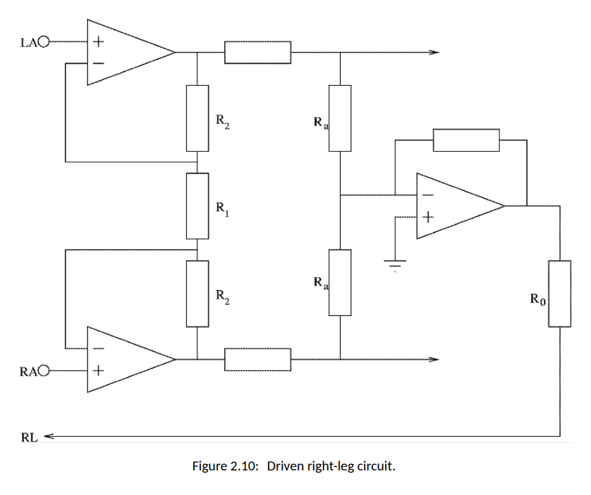
🔹 1. Sensing the Common-Mode Voltage
The LAO (left arm output) and RAO (right arm output) are fed into the two input amplifiers at the top left and bottom left of the diagram.
These signals contain both:
The ECG signal (what we want), and
Common-mode noise (what we don’t want).
Resistors labeled Ra are used to average these two signals, giving an estimate of the common-mode voltage on the body.
Because current entering a high-impedance op-amp input is almost zero (ideal op-amps), the node in between the resistors behaves like a passive averaging point:
This forms a resistive voltage divider.
Each side contributes equally, due to equal resistance.
So the voltage there is the mean of the two voltages.
🔹 2. Inverting the Noise
The averaged common-mode voltage is sent into the auxiliary op-amp on the right side of the diagram.
This amplifier inverts the signal — so any positive noise becomes negative and vice versa.
This inversion is key to cancelling the noise — like speaking in exact opposite phase to cancel out a sound wave.
🔹 3. Feeding It Back into the Right Leg (RL)
The inverted signal is passed through a safety resistor R₀ and delivered to the right leg electrode.
This injects a tiny current (less than 1 μA) into the body.
This current creates an opposing electric field that cancels out the noise field affecting the ECG electrodes.
🔹 4. Feedback Keeps the System Balanced
Because this is a feedback loop, the system constantly adjusts:
It watches for new noise,
Inverts it,
Injects a cancelling signal through the RL electrode.
This drives the common-mode voltage close to zero, improving signal clarity.
⚠ Safety Feature: R₀ Resistor
R₀ is very large (often several megaohms) to protect the patient.
If something goes wrong — like a surge in voltage — the high resistance limits the current to a tiny amount.
For example, with 10 V supply and 5 MΩ, the maximum current is:
This ensures no dangerous current can flow into the body.