Lab 201 Pre Reading Knowledge
Dental radiographs (X-rays) are a crucial diagnostic tool that allow clinicians to:
Detect caries (tooth decay) that are not visible clinically.
Assess periodontal bone levels.
Evaluate root and pulp health.
Diagnose infections, cysts, or tumours.
Aid in orthodontic and surgical planning.
Monitor treatment outcomes (e.g. root canal success)
X-rays are a form of electromagnetic radiation, produced in the X-ray tube head when high-speed electrons strike a metal target.
When X-rays pass through the body, some are absorbed (especially by dense structures like bone), while others pass through and hit the sensor, forming an image.
The amount absorbed depends on the tissue density, giving contrast in the radiograph.
Key takeaway: The contrast and clarity of the radiographic image depend on proper exposure, positioning, and technique.
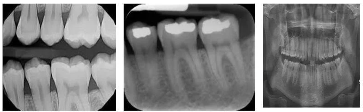
📸 Types of Dental Radiographs
Intraoral Radiographs (sensor/film placed inside the mouth):
Bitewing: interproximal caries, check underneath existing restoration and check for bone loss in periodontal disease
Periapical (PA): Captures the full tooth including apex and surrounding bone.
Occlusal: Taken from the occlusal plane, larger image of upper/lower jaw (to which film is parallel); sensor is detected from above/below
Extraoral Radiographs (sensor is outside the mouth):
OPG (Orthopantomogram): Panoramic image showing all teeth and jaw structures.
Lateral Cephalometric (Lat Ceph): saggital or side view; film is parallel to side of face, PID perpendicular to both, useful for orthodontics; becomes cephalometry when measurements are taken.
TMJ Imaging: Challenging due to bone interference, images of the joints connecting the jawbone to the skull; taken by radiographer
AP (Anteroposterior) View: used for a more coronal or ‘top’ view
Lateral Oblique Views: image taken from the side, at an angle; PID perpendicular to film
Hand-Wrist X-rays: Occasionally used in orthodontic growth assessment.
🧪 Radiographic Technologies
Conventional Film (rarely used now) :
Involves developing and fixing chemicals (toxic and temperature-sensitive).
Requires physical processing, which is time-consuming and environmentally hazardous.
Phosphor Plates (PSPs):
Thin, flexible image receptors.
Processed in a scanner (image appears in ~3 seconds).
Used widely in clinical settings and student clinics.
Charge-Coupled Devices (CCDs):
Provide immediate images.
Bulkier, rigid, and often uncomfortable due to thickness and attached cord.
Less patient-friendly but efficient in workflow.
Radiation Exposure:
Digital radiography (PSP and CCD) uses 1/3 to 1/4 the radiation dose of conventional film.
Lead aprons and thyroid collars are no longer required.
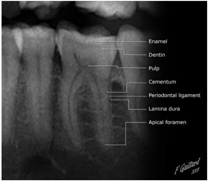
🧠 Radiographic Anatomy
To understand what you’re seeing on an X-ray, you need to recognise:
Teeth (enamel, dentine, pulp chamber).
Supporting structures (periodontal ligament space, lamina dura, alveolar bone).
Normal anatomical landmarks (e.g. mental foramen, nasal cavity, maxillary sinus, mandibular canal).
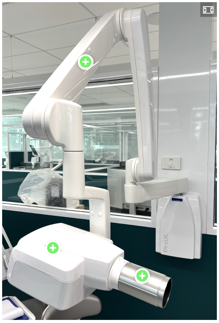
Radiography equipment
X-ray unit
Extension Arm (Articulating Arm)
Connects the control panel to the tube head.
Allows flexible movement and positioning of the tube head around the patient.
Locking joints hold the tube head in place during exposure.
Tube Head
This is the part that generates X-rays and directs them to the sensor.
Includes:
a) X-ray Tube
Produces X-rays by directing high-speed electrons at a tungsten target.
b) Transformer
Regulates voltage to power the X-ray tube.
c) Filtration (Aluminium Filter)
Removes low-energy X-rays that don’t contribute to the image, reducing patient exposure.
d) Collimator
A lead-lined disc or rectangular opening that shapes and limits the X-ray beam.
Reduces scatter radiation and improves image quality.
Position Indicating Device (PID)
Attached to the front of the tube head.
Also called the "cone".
Directs and shapes the X-ray beam toward the area of interest.
Types of PIDs:
Round or rectangular
Short, medium, or long (long PIDs reduce divergence and improve accuracy)
Open-ended (preferred, reduces scatter)
Aligns with the sensor holder's aiming ring for accurate beam alignment.
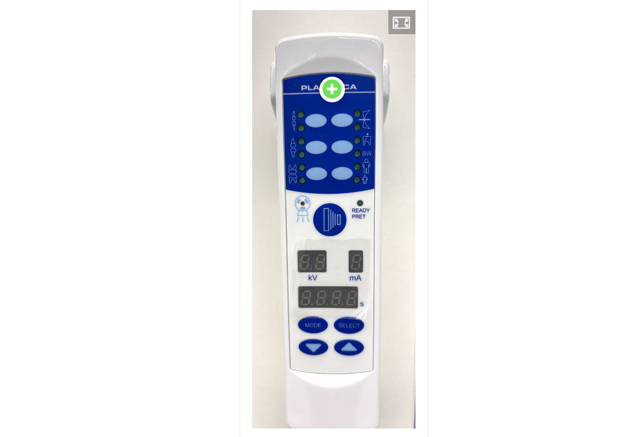
Control Panel
Wall-mounted or unit-integrated.
Allows the operator to adjust:
Exposure time
kVp (kilovoltage peak) – affects contrast
mA (milliamperage) – affects the amount of X-rays
Often has preset buttons for types of radiographs (e.g., bitewing, anterior PA).
Positioning devices
The "Rinn system" in dentistry refers to a range of intraoral imaging accessories to aid in accurate and efficient dental X-ray procedures. These accessories, including holders, aiming rings, and bite blocks, simplify the process of positioning film or sensors for optimal image quality. The system aims to improve patient comfort, reduce radiation exposure, and enhance diagnostic accuracy.
Benefits fo using positioning devices:
Improved Accuracy: Precise positioning reduces errors and retakes, leading to higher quality images and more accurate diagnoses.
Enhanced Patient Comfort: Some components, like the Uni-Grip 360, are designed with rounded corners and compact sizes to improve patient comfort during imaging.
Reduced Radiation Exposure: Proper positioning with the Rinn system can help minimize radiation exposure by ensuring accurate beam alignment.
Increased Efficiency: The streamlined workflow and fewer components can save time during dental X-ray procedures.
Digital and Traditional Imaging: The Rinn system is compatible with both digital sensors and traditional film or phosphor plates.
Key Components and Features:
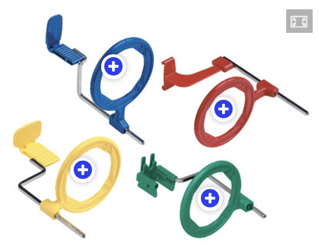
XCP (Extension Cone Paralleling) Instruments: These are a core part of the system, designed to hold film or sensors and align them with the X-ray beam for accurate paralleling technique.
Blue – Anterior (Front Teeth)
Used for periapical radiographs of anterior teeth (incisors and canines).
The blue holder positions the sensor vertically.
Often used with a smaller sensor (Size 1).
Red – Bitewing
Used for bitewing radiographs (usually for checking interproximal caries and bone levels).
The red holder positions the sensor horizontally.
Used in both premolar and molar regions.
Yellow – Posterior (Back Teeth)
Used for periapical radiographs of posterior teeth (premolars and molars).
The yellow holder positions the sensor horizontally.
Usually used with a Size 2 sensor.
Green – Endodontic
This is sometimes included in advanced kits.
Designed for endodontic procedures to accommodate files and rubber dams.
Usually has an open or split design to fit over instruments or clamps.
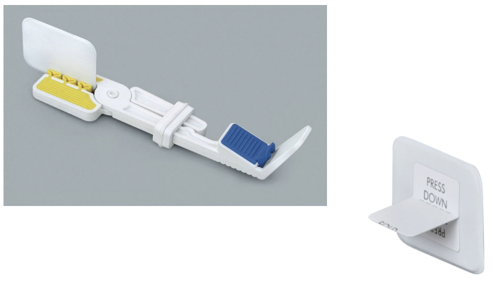
Kwik bite - designed to assist the alignment of the PID for taking bitewing radiographs
Sensor and Film Holders: Various holders, like the Snap-A-Ray and Bitewing tabs, are designed to securely hold different sizes of digital sensors and film or phosphor plates but they do not offer assistance with alignment.
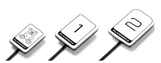
Digital Sensors and Phosphor Plates
These are the "image receptors" that capture the radiographic image when exposed to X-rays.
Digital Sensors: These are wired or wireless devices that instantly transmit the image to a computer. They're more sensitive to damage and need careful handling:
Always cover with a protective sheath.
Avoid biting pressure on the cable.
Handle gently to avoid cracking or malfunction.
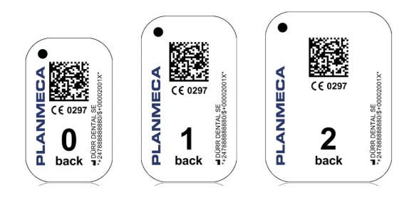
Phosphor Plates (PSPs): These resemble traditional X-ray film but must be scanned after exposure. They're flexible and more comfortable for the patient, but:
Must be shielded from light before scanning.
Can be scratched or damaged if mishandled.
Must be correctly oriented to avoid reversed images.
Regardless of the type, always check:
Orientation (which way the sensor should face)
Correct size for the area being imaged
Use of infection control barriers
Proper alignment in the holder
Summary of sizes and uses of the main film/sensor/plates
Size 0
20mm x 30mm
Children
5-6 y/o
Size 1
22mm x 35mm
Anterior periapical
Size 2
31mm x 41mm
Posterior periapical
Size 4
57mm x 76mm
Occlusal
‘Bitewing’ film
25mm x 53mm
Bitewings

Radiation Safety in Dental Practice
Minimise exposure by limiting the number and type of radiographs (e.g. avoid OPGs for single-tooth issues).
Digital radiography significantly reduces radiation dose compared to conventional film.
Safety measures include:
Regular X-ray machine servicing.
Use of proper filters and collimation (cone).
Lead aprons and thyroid collars are no longer required for routine dental radiography due to significantly reduced doses required for digital technology
Film holders (e.g. Rinn/AIM devices) should be used to avoid clinicians holding the film.
Maintain safe operator distance (at least 6 feet / wingspan) from the X-ray source.
Use radiation monitoring badges for staff may be used
Practices and operators must hold appropriate radiation licenses.
Adherence to occupational health and safety laws, including specific OHS regulations where applicable.
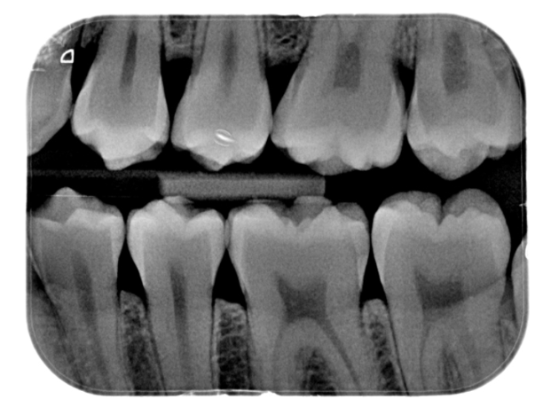
Characteristics of Dental X-Ray Images
Dental x-ray images are typically displayed in black, white, and shades of grey. When viewed on a lightbox or computer screen, the darkest areas appear black, and the lightest areas appear white. Two key terms are used to describe these variations:
Radiolucent: Areas that appear dark or black on the image. Radiolucent structures have low density, allowing x-rays to pass through them with little or no resistance. For example, air spaces appear radiolucent because they do not block x-ray beams.
Radiopaque: Areas that appear light or white on the image. Radiopaque structures are dense and absorb or resist x-ray beams. Examples include enamel, dentin, and bone, which all appear radiopaque due to their higher density.
These terms apply to both digital and film-based radiographs
An ideal dental image is neither too dark nor too light and should be diagnostic, meaning it provides sufficient detail for interpretation. Diagnostic images have:
Appropriate density (overall darkness)
Good contrast (difference between shades)
Clear sharpness
Minimal magnification or distortion
Accurate shape and size of the structures imaged
These visual and geometric qualities work together to ensure that the x-ray provides clear, accurate information for diagnosis and treatment planning.
X-rays pass through tissues in the mouth. Dense structures absorb more x-rays and appear lighter (radiopaque), while less dense structures let more x-rays through and appear darker (radiolucent) on the radiograph.
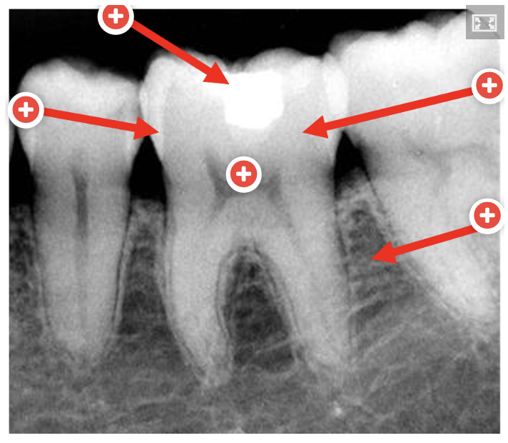
Fillings (Restorations)
Appearance depends on the type of material used:
Amalgam / Gold: Very radiopaque (bright white)
Modern Composite / Glass Ionomer: Light grey to white (varies by formulation)
Older Composite / Temporary fillings: May appear radiolucent or faint
These are man-made materials, so their radiopacity is often designed to help distinguish them clearly from natural tooth structure.
Enamel
Most radiopaque (bright white)
Very dense and highly mineralised (about 96% mineral).
Strongly absorbs x-rays → appears very white on x-rays.
Dentin
Moderately radiopaque (light grey)
Less dense than enamel (about 70% mineral).
Absorbs fewer x-rays than enamel → appears lighter than bone, but darker than enamel.
Pulp
Radiolucent (dark)
Contains soft tissue (nerves, blood vessels, no mineral content)
Not dense, so x-rays pass through easily
Appears as a dark or black area in the centre of the tooth
Bone
Mildly radiopaque (grey-white)
Contains mineral and marrow spaces → less dense overall.
Absorbs some x-rays but allows more to pass through → appears grey or mottled.
Dental Radiography terms
Radiographs
Images produced from an x-ray
Radiography
Science and process of taking a radiograph
Radiology
Interpretation of radiographs
Positioning indicator device (PID)
Head of the x-ray machine
Film/sensor/plate
Part of the x-ray that is placed in the patient’s mouth
Interproximal
Area between the teeth
Vertical angulation
How a PID may be pointed at an angle to the Buccal cusps (e.g. approx. 10˚ for a BW with tabs)
Horizontal angulation
How a PID should be perpendicular to to Buccal cusps (with film parallel), important for diagnosis of caries
Cone-cut
An error whereby part of image on radiograph is missing (caused by incorrect angle of PID)
Radiopacity
White areas on a radiograph, indicating more dense material (e.g. filling)
Radiolucency
Black areas on radiographs, indicating less dense material (e.g. air, pulp, caries)