Ultrasound Derivation
How can the pulse be modelled in ultrasound?
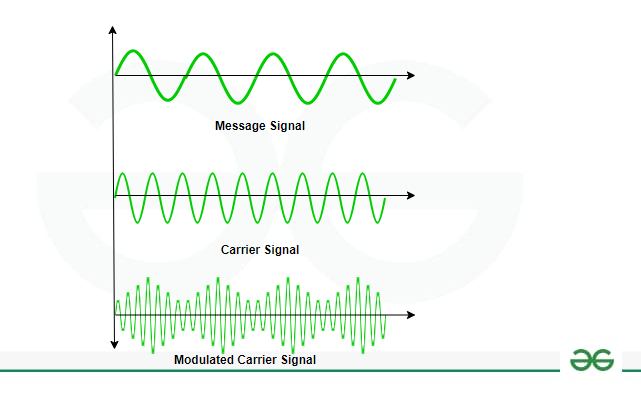
The pulse is modelled as:
This is a modulated signal, where:
: the envelope (shape) of the pulse over time (original freq).
: the new frequency of the ultrasound wave.
: the phase of the signal.
: represents a cosine-like oscillation inside the envelope.
This is a common way to represent ultrasound pulses mathematically—a high-frequency wave (carrier) inside a shaped pulse.
Why is it a carrier wave?
We send short pulses of ultrasound into the body.
But those pulses aren’t just "clicks" or single spikes. They are typically bursts of a sinusoidal wave (like a few cycles of a sine wave) modulated in amplitude to form a pulse.
Each transducer point acts as an acoustic dipole. This means each point on the transducer is treated as producing waves.
Calculating Pressure at Transducer - Part 1
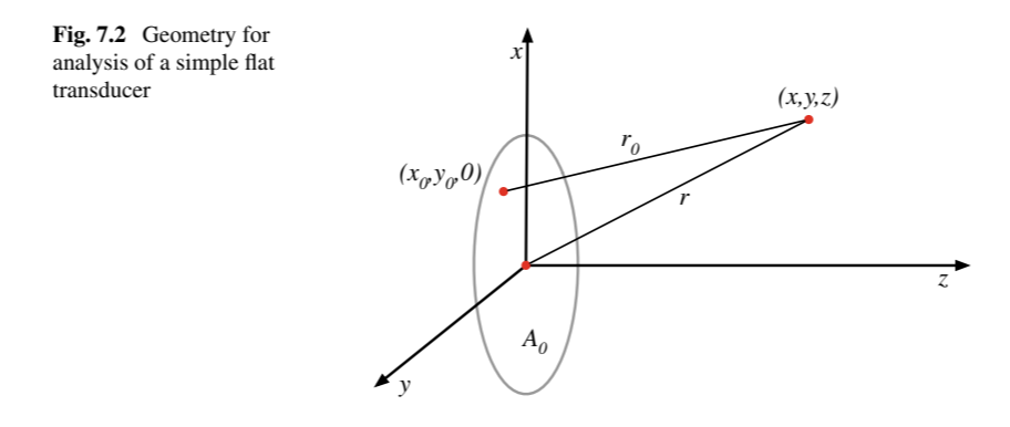
Geometry: Fig. 7.2
The transducer sits in the x–y plane (at ).
The point is a specific location on the transducer face.
is the point in space where we want to calculate the sound wave.
The distance between these points is , calculated using geometry.
Equation (7.3): Contribution from One Point
This gives the pressure wave (i.e., the sound signal) at point due to one small area on the transducer:
:
The straight-line distance from the source point on the transducer to the observation point .:
Accounts for the time delay—it takes time for the wave to travel a distance at speed (speed of sound).At , there should be no pressure experienced at that point as the wave hasn’t reached yet. This is why we shift it by this amount.
: This term accounts for the wave weakening with distance and with angle
Therefore,
Wave weakens with distance and with angle
🔹 Equation (7.4): Total Sound from Whole Transducer
This is the total sound at point , which is the sum of all contributions from every point on the transducer’s surface :
We integrate over the entire face of the transducer.
Each point contributes with its own delay and strength.
🧠 In Simple Terms:
The flat transducer is made of many tiny sources working together.
Each one sends out a delayed and scaled version of the pulse.
The sound at any point in space is the sum of all these delayed pulses.
This is how realistic ultrasound beams are formed—not just along a line, but spread in space with depth-dependent structure.