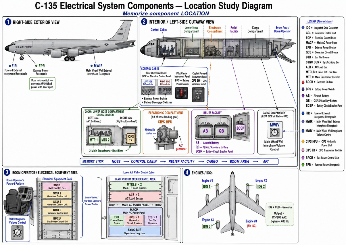
Electrical systems
Unit 4: Electrical Systems Electrical System Components, Operation and Switch Guards OBJECTIVE 4a: Without reference, identify basic facts and terms relating to electrical systems components and system operation and switch guards. A minimum of 11 out of 15 responses must be correct. INTRODUCTION The C-135 electrical system includes an Alternating Current (AC) and a Direct Current (DC) power supply system. These systems are further broken down into the battery power system, the Copilot’s Instrument Power Supply (CIPS) system, and the external power system. Each electrical system has its own control circuits to provide both automatic and manual operation and to also monitor and protect the electrical components in the AC and DC systems. Alternating Current (AC) Power Supply Components and System Operation Normal electrical power on the C-135 is used to operate aircraft systems and components. Power is applied by an external source or the Integrated Drive Generator (IDG) that produces 115/200 volts, 3 phase, and 400 hertz (frequency) AC electrical power. Integrated Drive Generator (IDG) IDGs consist of a constant speed drive (CSD) and a generator that produces 115/200 volt, 3 phase, and 400 hertz AC electrical power. The C-135 has three IDGs mounted on the accessory gearbox on engines 1, 2, and 3 (Figure 4-1). Figure 4-1 Integrated Drive Generator CUI CUI BLOCK V SG J3ABR2A534A018D 22 Generator Control Unit (GCU) The GCU provides protection for the AC power generating system by monitoring voltage, frequency (hertz), and paralleling (equal load division between generators) coming from the IDGs. A total of three GCUs are installed (one for each IDG) and are located on the electrical equipment rack next to the boom operators’ forward position (Figure 4-2 & 4-3). Figure 4-2 GCU Figure 4-3 GCU Electrical Control Panel The electrical control panel located on the pilot’s overhead panel contains switches and indicators for monitoring and controlling the AC and DC power supply systems (Figure 4-4). AC monitoring and control devices are located on the right side. Toggle switches operate power breakers in the main AC power panel. The paralleling selector switch selects the source of AC power being displayed on volt and frequency meters. DC monitoring and control devices are located on the left side of the panel. The ammeter and voltmeter selector switch selects source of DC power being displayed on volt and ammeter. CUI CUI BLOCK V SG J3ABR2A534A018D 23 Figure 4-4 Electrical Control Panel Main AC Power Panel The main AC power panel is located on the lower aft wall of the control cabin (behind the boom operators’ forward position (Figure 4-5 & 4-6). The panel receives power from the generators, auxiliary power unit (APU)/quick start APU system (QSAS), or an external power unit (-86). It contains all the breakers that are necessary to distribute AC electrical power. Figure 4-5 Main AC Power Panel CUI CUI BLOCK V SG J3ABR2A534A018D 24 BTB EPB Synchronizing Bus BTB BTB GCB GCB GCB Synchronizing Bus AC Load Busses Main TR Main TR AC Load Busses The AC load busses are located in the main circuit breaker panel above the main AC power panel, behind the boom operator’s forward position (Figure 4-6 & 4-8). The three AC load busses (one for each generator) are the distribution point for AC power to individual circuit breakers. Figure 4-6 Main AC Power Direct Current (DC) Power Supply Components and System Operation The power required to operate DC components is furnished by two main Transformer Rectifiers (TRs) or by two batteries in emergencies. (Aircraft Battery, QSAS Battery) Main TRs Two main TRs are located on the aft bulkhead on the left side of the lower nose compartment (Figure 4-7). They convert AC power input to 28 volts DC power output. Voltage from both units are connected to the respective main TR load busses and the switched DC bus. Figure 4-7 Main TRs CUI CUI BLOCK V SG J3ABR2A534A018D 25 Swtiched DC Bus Main TR Load Busses Two main TR load busses are located in the main circuit breaker panel above the main AC load busses (Figure 4-8). The main TR load busses are the distribution point for DC power to the individual circuit breakers. Figure 4-8 AC Load Buses and Main TR Load Buses Switched DC Bus The switched DC bus is located at the top of the electrical equipment rack next to the boom operator’s forward position (Figure 4-9). It contains circuit breakers for emergency and/or essential systems and components. The switched DC Bus receives power from battery or main TR units (depending on the battery power switch position). Figure 4-9 Switched DC CUI CUI BLOCK V SG J3ABR2A534A018D 26 Battery Power Switch The battery power switch determines the source of power supplied to the switched DC bus. It is a 3- position switch located on the pilot’s center instrument panel (Figure 4-10 & 4-11). When the switch is placed in: • Normal (up-position), the main TR units supply power to the switched DC Bus and main TR load busses. • OFF position (center position), no power is supplied. • Emergency (down-position), the battery supplies power to the switched DC bus and battery circuit breaker panel. Figure 4-10 Battery Power Switch Figure 4-11 Battery Power Switch Aircraft and Auxiliary (QSAS) Batteries The aircraft and auxiliary (QSAS) batteries provide power for emergency and/or essential DC equipment through the switched DC bus panel and the battery circuit breaker panel. Both of these batteries are located in the relief facility (Figure 4-12). Figure 4-12 Aircraft & Aux. Batteries CUI CUI BLOCK V SG J3ABR2A534A018D 27 In the event that one of the two batteries is depleted, the other battery can assume both loads by using the battery disengage switches. Both switches are located on the electrical control panel. Depressing either switch disconnects the selected battery and the remaining battery assumes both loads. The following are WARNINGS associated with battery removal and replacement: • Due to the weight of the batteries (90 lbs.), two personnel are required when removing and installing the batteries. • When transporting the batteries, always transport them with the connectors facing away from personnel to avoid an electrical current hazard. • You must always maintain clearance between connectors and grounding materials to avoid shock hazard. Battery Circuit Breaker Panel The battery circuit breaker panel is located on the outboard wall of the relief facility (Figure 4-13). This panel distributes battery power directly to individual circuit breakers for selected components/systems. The battery circuit breaker panel is the source of operating power for the interphone system. The interphone system is required between ground crew and control cabin while operating aircraft systems. Figure 4-13 Battery C/B Panel FWD EXTERNAL INTERPHONE RECEPTACLE. The forward external interphone receptacle is located on the right side of the fuselage next to the nose landing gear (Figure 4-14). The volume control for the forward external interphone receptacle is located at boom operator’s forward position (Figure 4-15). CUI CUI BLOCK V SG J3ABR2A534A018D 28 Figure 4-14 Fwd External Receptacle Figure 4-15 Volume Control MAIN WHEEL WELL EXTERNAL INTERPHONE RECEPTACLE. The main wheel well external interphone receptacle is located on the right side of the fuselage aft of the main landing gear wheel well door (Figure 4-16). Volume control for the main wheel well external interphone receptacle is located on the left side of the cargo compartment at station 870 (Figure 4-17). Figure 4-16 Main Wheel Well External Figure 4-17 Volume Control Copilot’s Instrument Power Supply (CIPS) CIPS provides a normal source of power for the copilot’s flight instruments; however, the main aircraft electrical system is used as an emergency source if the CIPS generator is inoperative. CIPS is controlled by a switch on the copilot’s forward instrument panel (Figure 4-18). CUI CUI BLOCK V SG J3ABR2A534A018D 29 Figure 4-18 CIPS Generator Switch Hydraulic Power Unit • Consists of a hydraulic motor and AC generator (Figure 4-19). • Located in the electronic compartment aft of nose landing gear. Figure 4-19 CIPS CUI CUI BLOCK V SG J3ABR2A534A018D 30 TR Unit • Converts AC power input to 28 volts DC power output. • Located on the right side, outboard wall of the lower nose compartment. External Power System External Power Breaker (EPB) The External Power Breaker connects external or APU electrical power to the synchronizing bus. The EPB is located inside the main AC power panel. (Figure 4-5 & 4-6) and is controlled manually by the external power switch on the electrical control panel (Figure 4-20) or automatically through the Bus Power Control Unit (BPCU) due to system malfunction. (Figure 4-21). Figure 4-20 EPB Bus Power Control Unit (BPCU) The Bus Power Control Unit is located on the electrical equipment rack next to the boom operator’s forward position (Figure 4-21). The BPCU receives its operating power from the switched DC bus. It contains a built-in-test feature with an error display window that will show any faults. The BPCU determines the quality of external power and indicates good quality by illuminating a green light on electrical control panel (Figure 4-20). It allows the external power breaker (EPB) to close if external power is within tolerance and opens the EPB if power goes out of tolerance. Figure 4-21 BPCU CUI CUI BLOCK V SG J3ABR2A534A018D 31 External Power Receptacle The external power receptacle is the connection point for the external power unit plug. It is located on the right side of the fuselage just aft of the nose landing gear wheel well (Figure 4-22). A micro switch inside the external power receptacle door prevents APU/QSAS power from being applied while the door is open. Figure 4-22 External Power Receptacle Switch Guards The purpose of switch guards is to protect against undesired system operation by covering the switch, thus preventing injury to personnel or damage to equipment. The function and design of switch guards vary depending on the level of protection needed. The C-135 mainly uses three types of switch guards (Figure 4- 23): • Black switch guards - cover the switch without affecting the switch position. • Red switch guards - cover the switch and force it to a specific position (normal for flight). • The shielded type - guards the sides of the switch to prevent accidental movement.