PRELIMINARY DESIGN
4.1 Introduction
The purpose of this chapter is to describe the preliminary design phase of an aircraft. Based on the systems engineering approach, an aircraft will be designed during three phases: (i) conceptual design phase, (ii) preliminary design phase, and (iii) detail design phase. At the conceptual design phase, the aircraft will be designed in concept without precise calculations. In other words, almost all the parameters are determined based on a decision-making process and selection technique. In contrast, the preliminary design phase tends to employ the outcomes of a calculation procedure. As the name implies, at the preliminary design phase, the parameters determined are not final and will be altered later. In addition, at this phase, parameters are essential and will influence the entire detail design phase directly. Therefore, ultimate care must be taken to insure the accuracy of the results of the preliminary design phase.
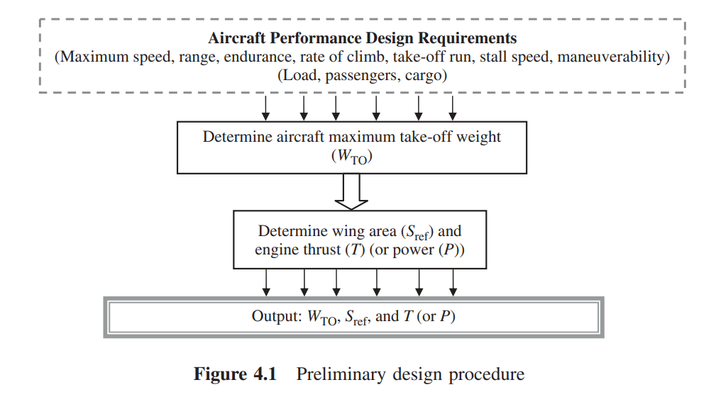
Three fundamental aircraft parameters determined during the preliminary design phase are: (i) aircraft maximum take-off weight (MTOW or WTO), (ii) wing reference area (SW or Sref or S ), and (iii) engine thrust (TE or T) or engine power (PE or P). Hence, three primary aircraft parameters of WTO, S , and T (or P) form the output of the preliminary design phase. These three parameters will govern the aircraft size, the manufacturing cost, and the complexity of calculations. If, during the conceptual design phase, a jet engine is selected, the engine thrust is calculated during this phase. But if, during the conceptual design phase, a prop-driven engine is selected, the engine power is calculated during this phase. A few other non-important aircraft parameters such as aircraft zero-lift drag coefficient and aircraft maximum lift coefficient are estimated during this phase too.
The preliminary design phase is performed in two steps:
• Step 1. Estimate aircraft MTOW.
• Step 2. Determine wing area and engine thrust (or power) simultaneously.
In this chapter, two design techniques are developed. First, a technique based on the statistics is developed to determine the wing reference area and engine thrust (or power).
Second, another technique is developed based on the air craft performance requirements (such as maximum speed, range, and take-off run) to determine the wing area and the engine thrust (or power). This technique is sometimes referred to as the matching plot or matching chart, due to its graphical nature. In some references, this process and this design phase are referred to as initial sizing. This is due to the nature of the process, which literally determines the size of three fundamental features of the aircraft.
Figure 4.1 illustrates a summary of the preliminary design process. In general, the first technique is not accurate (in fact, it is an estimation) and the approach may carry some inaccuracies, while the second technique is very accurate and the results are reliable.
4.2 Maximum Take-Off Weight Estimation
4.2.1 The General Technique
The purpose of this section is to introduce a technique to obtain the first estimate of the MTOW (or all-up weight) for an aircraft before it is designed and built. The word “estimation” is selected intentionally to indicate the degree of accuracy and reliability of the output. Hence, the value for the MTOW is not final and must be revised in the later design phases. The result of this step may have up to about 20% inaccuracies, since it is not based on its own aircraft data. But the calculation relies on other aircraft data with similar configuration and mission. Thus, we adopt past history as the major source of information for the calculations in this step. At the end of the preliminary design phase, the take-off weight estimation is repeated by using another more accurate technique which will be introduced in Chapter 10. As described in Chapter 1, the aircraft design nature is iterative, thus new data for the MTOW requires a new round of calculations and new designs for all aircraft components such as wing, tail, and fuselage.
Since the accuracy of the result of this design step depends largely on the past history, one must be careful to utilize only aircraft data that are current, with aircraft that are similar in configuration and mission. The currency of data and similarity play a vital role, as there are many aspects to compare. As the years pass, the science of materials and also manufacturing technologies are changing and improving. For instance, every year, new engineering materials are introduced to the market which are lighter and stronger. New materials such as composite materials have caused a revolution in the aircraft industry. In addition, new power transmission technologies such as fly-by-wire allow aircraft to be much lighter than expected. The trend is continuing, therefore, more current data results in a more reliable estimation.
Due to the fact that various aircraft manufacturing industries employ different approaches in their products, data from more than one aircraft must be obtained. The suggestion is to use data from at least five different aircraft to estimate the take-off weight of your aircraft. Aircraft manufacturing companies such as Boeing, Airbus, Lockheed, Grumman, Cessna, Raytheon, Bombardier, Dassult, Emberaer, Learjet, and Jetstream each have different management systems, design techniques, and market approaches. Thus, their aircraft productions have several differences, including MTOW. When you are selecting several aircraft for data applications, select aircraft from different companies and even from different regions of the world. Another recommendation is to choose aircraft data from recent years. For example, a comparison among fighters in the World War I era (e.g., Avro 504), the World War II era (e.g., Mustang and Spitfire), and the current modern advanced fighters (e.g., F-16 Fighting Falcon) demonstrates how much lighter the current aircraft are compared with older ones.
4.2.2 Weight Build-up
An aircraft has a range of weights from minimum to maximum depending upon the number of pilots and crew, fuel, and payloads (passengers, loads, luggage, and cargo). As the aircraft flies, the fuel is burning and the aircraft weight is decreasing. The most important weight in the design of an aircraft is the maximum allowable weight of the aircraft during take-off operation. This is also referred to as the all-up weight. The design MTOW or WTO is the total weight of an aircraft when it begins the mission for which it was designed. The maximum design take-off weight is not necessarily the same as the maximum nominal take-off weight, since some aircraft can be overloaded beyond design weight in an emergency situation, but will suffer a reduced performance and reduced stability. Unless specifically stated, MTOW is the design weight. It means every aircraft component (e.g., wing, tail) is designed to support this weight.
The general technique to estimate the MTOW is as follows: the aircraft weight is broken into several parts. Some parts are determined based on statistics, but some are calculated from performance equations.
The MTOW is broken into four elements:
1. Payload weight (WPL).
2. Crew weight (WC).
3. Fuel weight (Wf).
4. Empty weight (WE)
WTO = WPL + WC + WF + WE (4.1)
The payload weight and crew weight are mostly known and determined from the given data (by customer and standards), and not dependent on the aircraft take-off weight. In contrast, the empty weight and fuel weight are both functions of the MTOW. Hence, to simplify the calculations, both the fuel weight and the empty weight are expressed as fractions of the MTOW.
Hence:
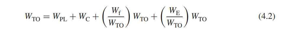
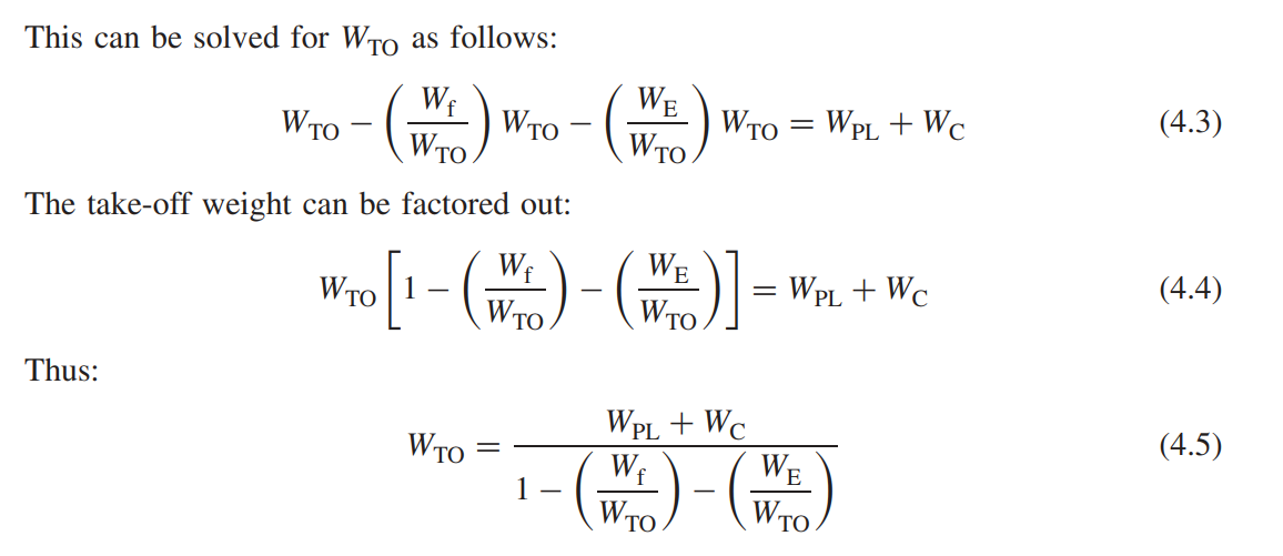 In order to find WTO, one needs to determine the four variables of WPL, WC, Wf /WTO, and WE/ WTO. The first three parameters, namely payload, crew, and fuel fraction, are determined fairly accurately, but the last parameter (i.e., empty weight fraction) is estimated from statistics.