Exhaustive Study Notes on Magnetic Effects of Electric Current
Foundations of Electromagnetism and Oersted's Discovery
Historical Discovery of Electromagnetism:
In , Danish physicist Hans Christian Oersted () accidentally observed that an electric current passing through a metallic wire caused a nearby compass needle to deflect.
This discovery proved that electricity and magnetism are interconnected phenomena rather than separate forces.
Oersted's work laid the groundwork for modern technologies, including radio, television, and fiber-optic communication systems.
The standard unit of magnetic field strength is named the oersted in his honor.
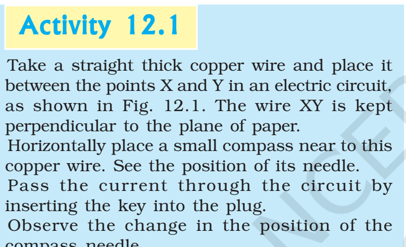
Demonstration of Current-Induced Magnetic Field (Activity 12.1):
Procedure:
A straight, thick copper wire is connected between points and in a simple electric circuit comprising a battery, resistor, and plug key.
The wire is oriented perpendicular to the plane of the paper.
A small magnetic compass is placed horizontally adjacent to the copper wire.
The plug key is inserted into the circuit to allow current to flow through the wire .
Observation:
Upon closing the circuit, the compass needle immediately deflects from its resting position.
Conclusion:
Flowing electric charges generate a magnetic field in the surrounding space.
Magnetic Fields and Field Lines
Properties of Magnetic Compass Needles:
A compass needle functions as a small, freely pivoted bar magnet.
When resting freely, its ends align along the Earth's approximate north-south direction.
North Pole (North-Seeking End): The end of the needle pointing toward geographical north.
South Pole (South-Seeking End): The end pointing toward geographical south.
Law of Magnetic Poles: Like magnetic poles repel one another ( or ), whereas unlike poles attract ( or ).
Concept of a Magnetic Field:
Definition: The region surrounding a magnet where its magnetic influence or force can be detected by other magnetic substances or moving charges.
Nature: Magnetic field is a vector quantity possessing both magnitude and direction.
Visualizing Magnetic Fields with Iron Filings (Activity 12.2):
Procedure:
A sheet of white paper is attached to a drawing board using adhesive material.
A bar magnet is placed at the center of the paper.
Iron filings are sprinkled uniformly around the bar magnet using a salt sprinkler.
The drawing board is gently tapped a few times.
Observation:
The iron filings align themselves spontaneously along curved pathways surrounding the magnet.
Explanation:
The bar magnet exerts magnetic force in its surrounding space, inducing transient magnetic dipoles in the iron filings.
The filings rotate and align along specific pathways known as magnetic field lines.

Mapping Field Lines Using a Magnetic Compass (Activity 12.3):
Procedure:
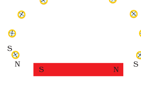
Fix a sheet of paper on a board and place a bar magnet in the center, tracing its boundary.
Place a small compass near the North pole of the bar magnet.
The South pole of the compass needle points toward the magnet's North pole, while its North pole points away.
Mark the positions of the two ends of the needle with fine dots on the paper.
Move the compass so its South pole occupies the position previously occupied by its North pole, and mark the new North pole position.
Repeat this step iteratively until reaching the South pole of the magnet.
Join the plotted dots with a smooth continuous curve to form a magnetic field line.
Plot multiple lines originating from different points around the magnet poles.
Observation:
Deflection of the compass needle increases continuously as it approaches either pole of the magnet.
Key Characteristics of Magnetic Field Lines:
Direction of Field Lines:
External to the magnet: Field lines emerge from the North pole and merge at the South pole.
Internal to the magnet: Field lines travel internally from the South pole to the North pole.
Magnetic field lines form continuous closed curves.
Relative Strength:
The relative strength of the magnetic field is proportional to the spatial density (closeness) of the field lines.
The field is strongest near the poles where lines are crowded together, resulting in greater magnetic forces on external magnetic materials.
Non-Intersection Principle:
No two magnetic field lines can ever cross or intersect each other.
Proof by contradiction: If two lines intersected at a point, placing a compass needle at that exact intersection would require the needle to point in two different directions simultaneously, which is physically impossible.
Magnetic Field Generated by Current-Carrying Conductors
Directional Reversal of Field with Current (Activity 12.4):
Procedure:
A long, straight copper wire is connected in series with two or three cells and a plug key.
The wire is placed parallel to and directly over a magnetic compass needle.
When current flows from North to South, the North pole of the compass needle moves toward the East.
Reversing the cell connections causes current to flow from South to North.
With reversed current, the North pole of the compass needle deflects in the opposite direction, toward the West.
Conclusion:
Reversing the direction of electric current completely reverses the direction of the magnetic field generated.
Field Pattern Around a Straight Conductor (Activity 12.5):
Procedure:
Pass a long, straight, thick copper wire vertically through the center of a fixed horizontal rectangular cardboard.
Connect the wire vertically between points and in series with a battery, an ammeter (), a variable resistor (rheostat), and a plug key.
Sprinkle iron filings uniformly over the horizontal cardboard surface.
Close the key, adjust the current, and gently tap the board.
Observations:
The iron filings arrange themselves into a pattern of concentric circles centered on the conducting wire.
The concentric circles represent the magnetic field lines surrounding the straight wire.

Mathematical Relationships and Dependencies:
Dependence on Current Strength ():
Increasing the current passing through the conductor increases the magnitude of needle deflection at a fixed point.
The magnitude of the magnetic field () produced at any given point is directly proportional to the current ():
Dependence on Distance ():
Moving the compass farther away from the conducting wire causes needle deflection to decrease.
The concentric circular field lines become larger and spread wider as distance () from the wire increases.
The magnitude of the magnetic field is inversely proportional to the radial distance ():
Right-Hand Thumb Rule (Maxwell's Corkscrew Rule):
Statement: Imagine holding a current-carrying straight conductor in your right hand such that your thumb points in the direction of conventional electric current flow. Your fingers will then naturally curl around the conductor in the direction of the magnetic field lines.
Maxwell's Corkscrew Analogy: If driving a right-handed corkscrew advances its tip along the direction of current flow, the rotational direction of the handle gives the direction of the magnetic field.

Worked Example 12.1:
Problem: Electric current flows through a horizontal power line in an East-to-West direction. Determine the direction of the magnetic field at a point directly below it and at a point directly above it.
Solution:
Applying the Right-Hand Thumb Rule with the thumb pointing West:
Looking at the system from the East end, the field lines curl in a clockwise direction in a plane perpendicular to the wire.
Looking at the system from the West end, the field lines curl in an anti-clockwise direction.
Therefore, directly below the wire, the field points toward the South; directly above the wire, the field points toward the North.
Magnetic Fields in Circular Loops and Solenoids
Magnetic Field of a Current-Carrying Circular Loop:
When a straight conductor is bent into a circular loop, the concentric field lines around every segment of the wire expand as distance from the wire increases.
At the center of the loop, the arcs of these large circles flatten out and appear as parallel straight lines.
By applying the right-hand rule across all segments, every section of the loop contributes to field lines pointing in the same uniform direction inside the loop.

Effect of Multiple Turns in a Coil (Activity 12.6):
If a circular coil contains closely wrapped turns of wire, the resulting magnetic field strength is times larger than that of a single turn coil carrying the same current:
Reason: Current in every circular turn flows in the identical direction, causing the individual magnetic field vectors from each turn to add up algebraically.
Magnetic Field Due to Current in a Solenoid:
Definition: A long coil containing a large number of circular turns of insulated copper wire wrapped closely into the shape of a cylinder is called a solenoid.
Field Pattern Characteristics:
The external magnetic field pattern of a current-carrying solenoid is identical to that of a bar magnet.
One end of the solenoid acts as a magnetic North pole, while the opposite end acts as a magnetic South pole.
Interior Field: Inside the solenoid, magnetic field lines form parallel straight lines, indicating that the magnetic field is completely uniform (equal magnitude and direction at all interior points).

Electromagnets:
Definition: A temporary magnet formed by inserting a soft iron core into the center of a current-carrying solenoid coil.
The strong, uniform magnetic field produced inside the solenoid magnetizes the soft iron core material effectively.
Force on a Current-Carrying Conductor in a Magnetic Field
Ampère's Hypothesis:
French scientist André-Marie Ampère () posited that if a current-carrying conductor exerts a magnetic force on a magnet, the magnet must exert an equal and opposite force on the current-carrying conductor.
Experimental Verification (Activity 12.7):
Procedure:
A light aluminium rod (length approximately ) is horizontally suspended by two wires connected to a stand.
A strong horseshoe magnet is positioned such that rod lies between its poles, with the North pole vertically below and South pole vertically above (field directed vertically upwards).
Rod is connected in series with a battery, key, and rheostat.
Current is passed through rod from end to end .
Observations:
The aluminium rod displaces horizontally to the left upon passing current.
Reversing current flow (from to ) causes the rod to displace to the right.
Reversing the magnet poles (field directed vertically downward) reverses the direction of force and displacement.
Key Principles:
A magnetic field exerts a mechanical force on a conductor carrying electric current.
The direction of force depends on both current direction and magnetic field direction.
Maximum Force: The magnitude of force is greatest when the direction of electric current is perpendicular () to the direction of the magnetic field.

Fleming's Left-Hand Rule:
Statement: Stretch the thumb, forefinger, and middle finger of your left hand such that all three are mutually perpendicular to one another:
Forefinger: Points in the direction of the Magnetic Field.
Middle Finger: Points in the direction of conventional Electric Current.
Thumb: Points in the direction of Motion or mechanical Force acting on the conductor.
Practical Devices Utilizing Magnetic Forces:
Electric motors, electric generators, loudspeakers, microphones, and electrical measuring instruments.

Worked Example 12.2:
Problem: An electron enters a magnetic field directed horizontally to the right, with the electron moving vertically downward. Determine the direction of force acting on the electron.
Solution:
Because electrons carry negative charge, conventional electric current flows opposite to electron motion (vertically upward).
Applying Fleming's left-hand rule (Forefinger to the right, Middle finger pointing upward):
The thumb points into the plane of the page.
Correct Answer: Option (d) into the page.
Magnetism in Human Medicine
Biological Magnetic Fields:
Electric currents flowing inside living organisms generate magnetic fields.
Ion currents traveling along biological nerve cells produce extremely weak magnetic fields during neural transmission.
Biological magnetic field strengths are roughly one-billionth () the strength of the Earth's magnetic field.
Key Organs and Medical Imaging:
The two primary human organs producing significant biological magnetic fields are the heart and the brain.
Magnetic Resonance Imaging (MRI): A non-invasive diagnostic technique that uses internal body magnetic fields to generate high-resolution cross-sectional images of anatomical structures.
Domestic Electric Circuits and Safety Systems
Mains Supply Wire Specifications:
Live Wire (Positive): Covered with red insulation; carries high potential.
Neutral Wire (Negative): Covered with black insulation; kept at ground potential ().
Potential Difference: In standard domestic power supplies, the potential difference between live and neutral wires is with an Alternating Current (AC) frequency of
Earth Wire: Covered with green insulation; connected to a heavy metal plate buried deep underground near the residence.
Domestic Power Lines and Wiring Layout:
Power passes from overhead poles or underground cables into the house meter-board through the Electricity Board's main fuse, an electricity meter, and a main distribution switch.
Two Separate Circuits:
Current Rating Circuit: Supplies high-power appliances such as geysers, air coolers, and washing machines.
Current Rating Circuit: Supplies low-power appliances such as light bulbs, fans, and televisions.
Parallel Connection: Appliances are connected parallel to one another across live and neutral wires so that every appliance receives an equal potential difference of and operates independently with its own ON/OFF switch.

Circuit Protection Measures:
Earthing Safety Mechanism:
Provides a ultra-low resistance conducting pathway directly to ground for metal-bodied appliances (e.g., electric press, toaster, refrigerator).
If insulation fails and live wire contacts the metallic shell, current flows safely into Earth without raising the potential of the metal body, preventing fatal electric shocks to users.
Short-Circuiting:
Occurs when damaged wire insulation or appliance faults allow live and neutral wires to touch directly.
Circuit resistance drops close to zero, causing current to spike abruptly, generating intense heat and potential fire hazards.
Overloading:
Occurs when total power consumption exceeds safe circuit current limits due to direct contact, voltage spikes, or connecting too many appliances to a single wall socket.
Electric Fuse Operation:
Safety component made of a wire with a low melting point connected in series with the live wire.
When current exceeds safe thresholds, excessive Joule heating () rapidly melts the fuse wire, breaking the circuit and stopping current flow to protect appliances from damage.
Questions, Worked Solutions, and Concept Check
Question 1: Why does a compass needle get deflected when brought near a bar magnet?
Solution: A compass needle is a small bar magnet itself. When brought near another bar magnet, the two magnetic fields interact, exerting a mechanical force that deflects the needle.
Question 2: Draw magnetic field lines around a bar magnet. List their properties. Why don't two magnetic field lines intersect each other?
Solution:
Properties: Continuous closed curves; emerge from N pole and merge at S pole externally; density of lines indicates field strength; lines never intersect.
Non-intersection: If field lines crossed, a compass needle placed at the intersection point would point in two different directions simultaneously, which is impossible.
Question 3: Consider a circular loop lying in the plane of a table with clockwise current flow. Determine magnetic field direction inside and outside the loop.
Solution: Applying the Right-Hand Thumb Rule, for a clockwise current, magnetic field lines enter downward (into the table surface) inside the loop, and point upward (out of the table surface) outside the loop.
Question 4: The magnetic field inside a long straight solenoid-carrying current is:
(a) zero.
(b) decreases as we move towards its end.
(c) increases as we move towards its end.
(d) is the same at all points.
Solution: Correct option is (d) (the field is uniform throughout the interior).
Question 5: In Activity 12.7, how will displacement of rod change if: (i) current is increased, (ii) a stronger magnet is used, (iii) length of rod is increased?
Solution: In all three cases (i, ii, and iii), the magnetic force acting on the conductor increases, causing larger displacement of rod .
Question 6: A positively-charged particle (alpha-particle) projected towards west is deflected towards north by a magnetic field. The direction of magnetic field is:
(a) towards south (b) towards east (c) downward (d) upward
Solution: Positive charge moving West implies conventional current direction is West. Deflection North means force is North. Applying Fleming's left-hand rule, magnetic field points (d) upward.
Question 7: Name two safety measures commonly used in domestic electric circuits.
Solution: Electric fuse and Earthing system.
Question 8: An electric oven of power rating is operated in a domestic circuit with a current rating. What result do you expect? Explain.
Solution:
Calculate operating current:
Since , the current drawn exceeds the circuit's safe rating, overloading the circuit and causing the electric fuse to melt and break the circuit.
Question 9: What precautions should be taken to avoid overloading domestic electric circuits?
Solution: Avoid connecting multiple high-power appliances into a single power socket; do not operate high-wattage devices simultaneously on a low-rating circuit; inspect wire insulation regularly; use properly rated electric fuses.