Weight and Balance
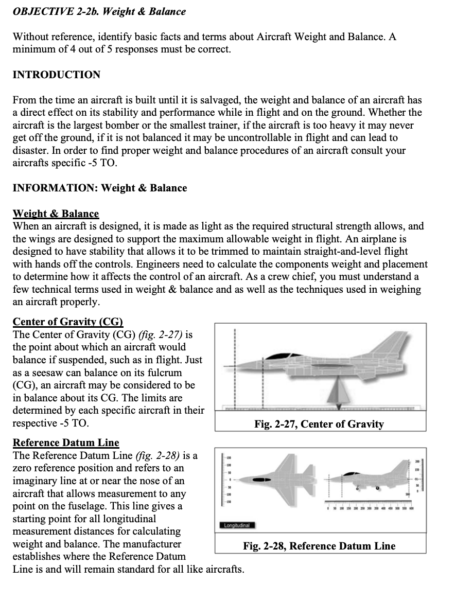
OBJECTIVE 2-2b. Weight & Balance Without reference, identify basic facts and terms about Aircraft Weight and Balance. A minimum of 4 out of 5 responses must be correct. INTRODUCTION From the time an aircraft is built until it is salvaged, the weight and balance of an aircraft has a direct effect on its stability and performance while in flight and on the ground. Whether the aircraft is the largest bomber or the smallest trainer, if the aircraft is too heavy it may never get off the ground, if it is not balanced it may be uncontrollable in flight and can lead to disaster. In order to find proper weight and balance procedures of an aircraft consult your aircrafts specific -5 TO. INFORMATION: Weight & Balance Weight & Balance When an aircraft is designed, it is made as light as the required structural strength allows, and the wings are designed to support the maximum allowable weight in flight. An airplane is designed to have stability that allows it to be trimmed to maintain straight-and-level flight with hands off the controls. Engineers need to calculate the components weight and placement to determine how it affects the control of an aircraft. As a crew chief, you must understand a few technical terms used in weight & balance and as well as the techniques used in weighing an aircraft properly. Center of Gravity (CG) The Center of Gravity (CG) (fig. 2-27) is the point about which an aircraft would balance if suspended, such as in flight. Just as a seesaw can balance on its fulcrum (CG), an aircraft may be considered to be in balance about its CG. The limits are determined by each specific aircraft in their respective -5 TO. Reference Datum Line The Reference Datum Line (fig. 2-28) is a zero reference position and refers to an imaginary line at or near the nose of an aircraft that allows measurement to any point on the fuselage. This line gives a starting point for all longitudinal measurement distances for calculating weight and balance. The manufacturer establishes where the Reference Datum Line is and will remain standard for all like aircrafts. Fig. 2-27, Center of Gravity Fig.
Arm The arm is the longitudinal (horizontal) distance that a part of the aircraft (weight) is located from the reference datum line. When the arm for a piece of equipment is being determined, the measurement is taken in inches from the reference datum line to the center of gravity of any particular item (weight). Moment Moment (fig. 2-29) is the product of a weight multiplied by its distance from the reference datum line (Arm). When an object’s weight is multiplied by its arm, the result is known as its moment and is expressed in either foot-pounds or inch-pounds. In other words, moment is a downward force which results from an objects weight acting at a distance. Mean Aerodynamic Chord The Mean Aerodynamic Chord (MAC) (fig. 2-30) is located on the longitudinal axis (axis that runs from the aircrafts nose to tail) of the aircraft and is normally associated with the CG for flight characteristics. The MAC is the center point of the lateral axis rotation usually centered between the leading edge and trailing edge of the wing. Most aircraft wings are not a perfect rectangle, therefore, MAC is usually calculated and expressed in percent. Ballast Ballast is weight placed in specific areas of an aircraft to adjust center of gravity along with the MAC to ensure stability of flight and favorable flight characteristics. Ballast can be permanently installed or removed to obtain proper aircraft’s CG and MAC Weighing equipment The key information for determining weight distribution is knowing how much the aircraft weighs at specific locations. This helps to determine the amount of payload that can be added to the aircraft without exceeding maximum takeoff weight. There are two devices used to weigh aircraft, either scales or load cells. Using scales, aircraft are positioned on drive-up scales (fig. 2-31) by towing them onto the scales. The weight exerted on each wheel assembly is recorded and analyzed to calculate the aircraft weight and CG. The other procedure is to position the aircraft on jacks fitted with load cells (specialized measuring devices), which transmit each cells’ results to a readout device to calculate weight and CG. Fig. 2-31, Weighing Aircraft Fig. 2-30, MAC Fig. 2-29, Moment CUI//Rel To USA, AF, AR, BL, BR, CI, CO, EC, ET, ASFF (H5 and J3), FR, GB, HO, ID, IQ, JO, KU, MX, NK, NI, PE, PI, RO, SR, TU, TK AND UY CUI//Rel To USA, AF, AR, BL, BR, CI, CO, EC, ET, ASFF (H5 and J3), FR, GB, HO, ID, IQ, JO, KU, MX, NK, NI, PE, PI, RO, SR, TU, TK AND UY Block II SG J3ATR2AX3X 048C 56 SUMMARY The weight and arm can move the CG within safe allowable limits. Maintenance personnel must be aware of any weight changes and the arm of those changes. To maintain the weight and balance of assigned aircraft the crew chief is the one maintainer who ensures equipment is secured in its proper place. They also need to ensure the aircraft’s fuel, oil, hydraulic fluid, and other fluids are properly filled not only for proper operations of the systems, but for the weight and balance in flight as well.