Interfaces and Storage Protocols
PATA
Parallel ATA used parallel communication and preceded serial communication. It
SATA
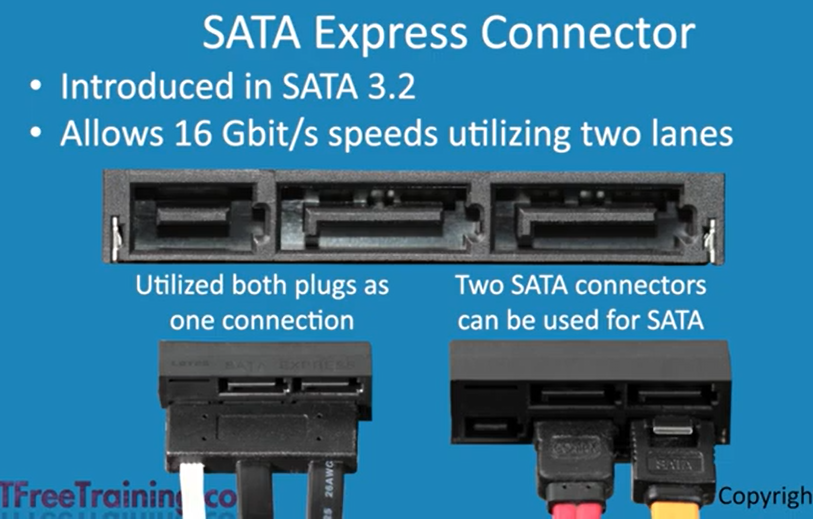
Serial ATA, SATA replaced PATA has three versions, SATA I, SATA II, & SATA III. SATA 3 tops out at 6 GB/s but SATA 3.2 introduced SATA Express (SATAe) which uses PCIe lanes to increase data transfer rate. SATAe connects SSDs directly to a PCs PCI express lanes. Another thing to note is that SATA 3.2 is not significantly affected by overhead created by encoding because it uses a more efficient encoding method.
There are SSD SATA Express drives that plug directly into the PCIe slot. There aren’t many drives that use the SATAe cable to take advantage of the PCIe lanes, but the slots that I have seen use two of the SATA 7 pin cables and power connector. It’s not used much, never really was, and hard to find the connectors.
eSATA
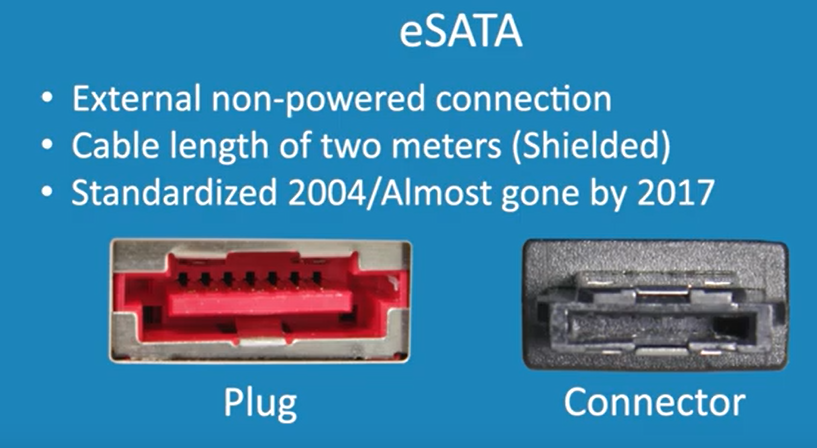
External SATA is the external non-powered version of SATA
mSATA
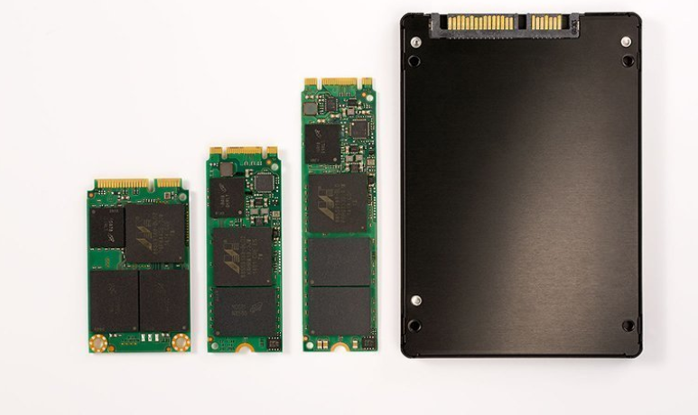
mSATA, on the left, stands for Mini-SATA (serial advanced technology attachment) used primarily in laptops and tablets. It doesn’t use the M.2 form factor, instead it measures typically 30mm x 50mm. Even though it will physically fit in a mini PCIe slot it is not electronically compatible with the mini PCIe slot because it needs SATA signaling. Some laptops provide both mini PCIe and mSATA support. So mSATA will only work in a mini PCIe slot if its designed for mSATA. mSATA follows the SATA standard meaning it has the same performance limits and capabilities as traditional SATA drives.
HDD
Hard disk drives also known as magnetic drives also use the SATA interface
Latency: the time it takes for the read/write head to access the desired sector of the disk which is dependent on the rotational speed of the disk (RPM). Usually latency for a HDD is calculated by adding rotational latency and seek time. Rotational latency is calculated as half the time it takes for a full revolution. Ex: for a 7,200 RPM average rotational latency would be 4.17, for a 10,000 RPM it would be about 3 milliseconds. Seek time is the time it takes for the read/write head to move to the correct track on the disk where the data is located
AHCI
Advanced Host Controller Interface, introduced in 2004, is a type of hardware that defines how the SATA interface communicates with the computer’s motherboard. AHCI replaced IDE (integrated drive electronics) which was designed for legacy systems with parallel ATA interfaces. AHCI might need to be enabled in the BIOS/UEFI settings, which has native support in Windows, Linux, macOS. AHCI cannot be used with NVMe. AHCI was never built to run SSDs instead was designed to run with SATA hard drives and therefore will never be optimized for SSDs, although it will still work with SATA SSDs.
PCIe
Peripheral Component Interconnect Express - A type of serial expansion bus standard used to connect components like GPUs, Ethernet cards, WiFi cards, and SSD storage drives to the motherboard.
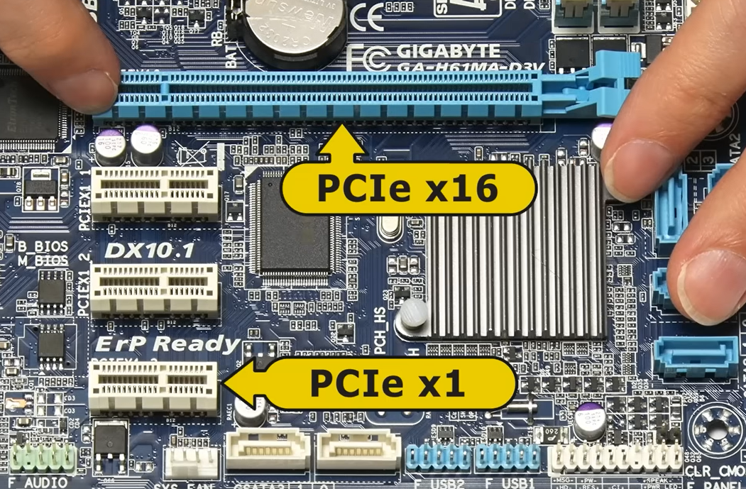
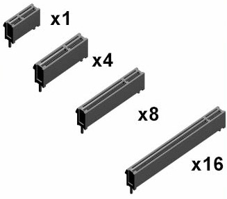
There are five common types of PCIe slots, x1, x2, x4, x8, and x16, each number representing the number of lanes on the card or slot. The more lanes the more data can travel on them and higher potential rate of data transfer.
PICe Versions (data rate roughly doubles each version)
2004: PCIe 1.0 - 250 MB/s per lane
2007: PCIe 2.0 - 500 MB/s per lane
2010: PCIe 3.0 - 985 MB/s per lane
2017: PCIe 4.0 - 1.97 GB/s per lane
2019: PCIe 5.0 - 3.94 GB/s per lane
2021: PCIe 6.0 -
Peripherals have different pins so a x1 peripheral can probably fit in a x16 slot
There are SSD SATA Express drives that plug directly into the PCIe slot. There aren’t many drives that use the SATAe cable to take advantage of the PCIe lanes, but the slots that I have seen use two of the SATA 7 pin cables and power connector. It’s not used much and hard to find the connectors.
M.2 Form-Factor
Both NVMe and SATA M.2 SSD are Solid State drives that use the M.2 form factor. NVMe uses the PCIe bus and SATA M.2 uses the SATA bus.The M.2 slot is designed to support both SATA and PCIe.
M.2 SATA SSD
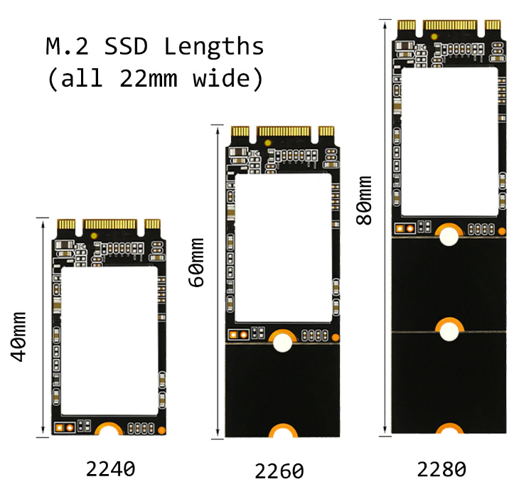
When an M.2 SATA SSD is inserted, the M.2 connector routes its data lines to the motherboard’s SATA controller just like a 2.5” SATA drive. The drives protocol determines how it operates, either SATA or NVMe. M.2 SATA SSD operates just like a 2.5” SATA SSD it just connects directly to the motherboard using the M.2 form factor and also comes in different sizes
NVMe SSD
Non-Volatile Memory Express SSDs use the PCIe lanes allowing it to surpass the SATA transfer rate cap of 6 Gbps, allowing SSDs to unleash their true potential. As you’ll see below, M.2 NVMe is limited to only a maximum of 4 PCIe lanes despite PCIe protocol supporting up to 16 lanes, this is because M.2 slots are designed for compact, high-performance devices
M.2 Keying Notches
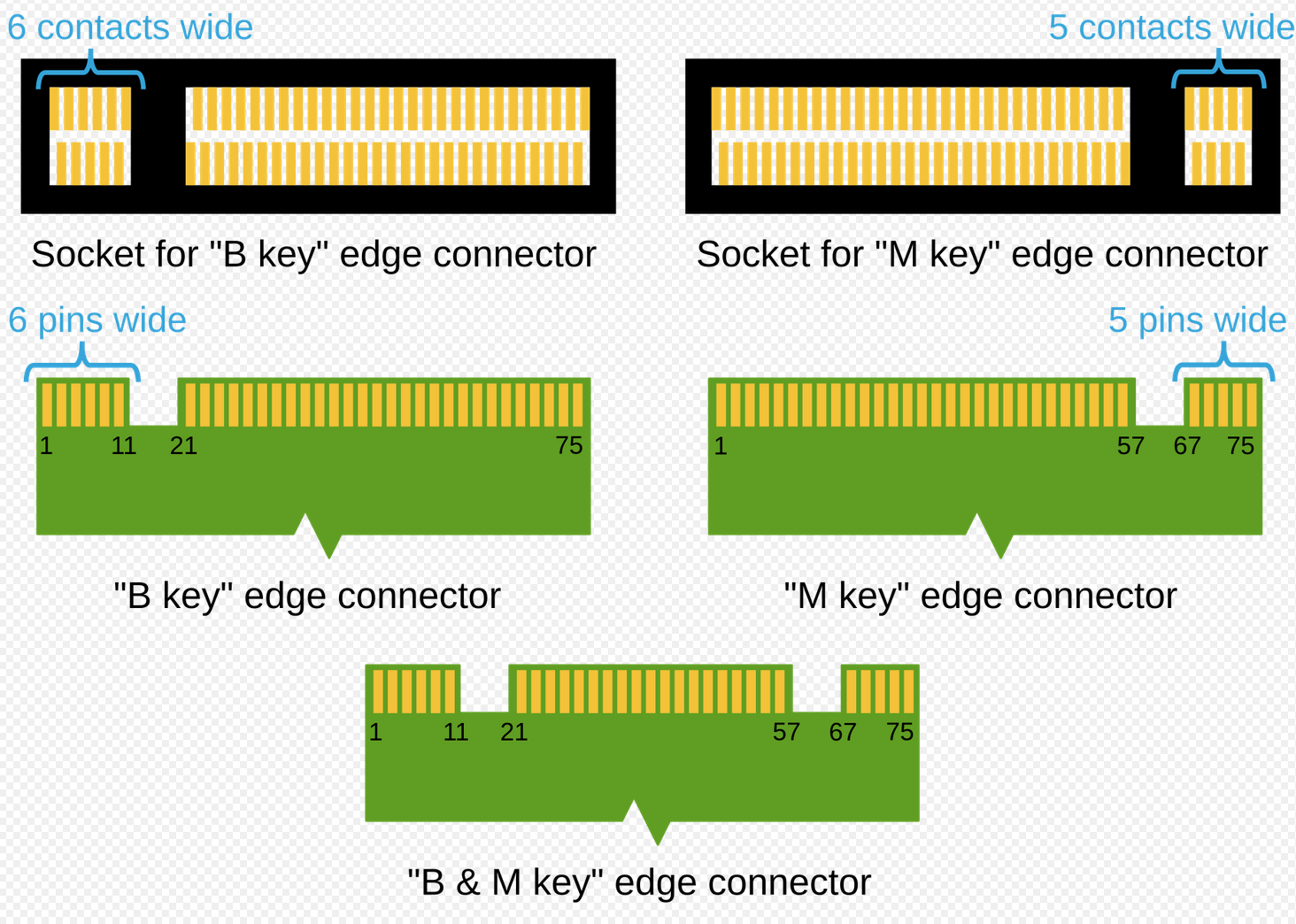
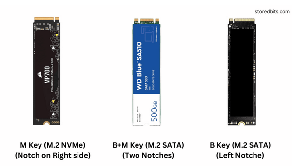
The M.2 connectors keying notches determine what kind of data protocol (PCIe, SATA, USB, etc.) the drive supports
B-Key: Allows SATA or PCIe x2 lanes
M-Key: Supports PCIe x4 lanes, enabling higher data transfer speeds, often used for NVMe drives
B+M Key: Compatible with both B-Key and M-Key slots, offering versatility. These drives typically use PCIe x2 or SATA interfaces but are not as fast as M-Key drives
Other M.2 Keying Notches not necessary to memorize:
Key A: Typically used for Wi-Fi and Bluetooth cards
Key E: Also used for wireless modules