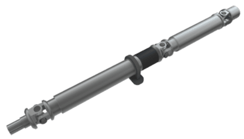
Characteristics of a Driveshaft Assembly
Double Cardan Joint
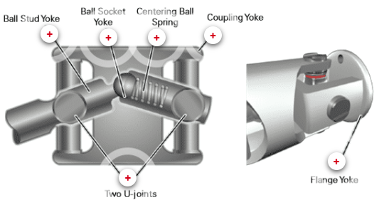
Ball Stud Yoke
Welded to the driveshaft, providing a direct connection between the driveshaft and the U-joint.
The inner section of the yoke is a stud that fits into the centering ball.
This connection mechanically links the ball stud yoke and the flange yoke, allowing proper articulation and torque transfer in the driveline.
Supports smooth rotation while accommodating angular changes in the driveshaft.
Ball Socket Yoke
Connects the ball stud yoke and flange yoke, acting as a pivot point.
Allows the driveshaft to transfer motion smoothly between sections while accommodating angular changes.
When the front section of the driveshaft moves, it causes the opposite section to move in the opposite direction, maintaining consistent power transfer and reducing vibration.
Centering Ball Spring
Presses firmly against the ball located between the two driveshafts.
Holds the ball securely in the socket, maintaining proper tension.
Prevents the centering ball from moving back and forth, which would otherwise cause clunking noises in the driveshaft.
Ensures smooth operation and consistent power transfer between the connected driveshaft sections.
Coupling Yoke
Acts as a carrier connecting and holding two simple U-joints together.
Enables the driveshaft to operate at greater angles than a single U-joint could handle.
Helps prevent vibrations when the suspension moves over variable road surfaces.
Supports smooth power transfer while accommodating driveline angular changes.
Two U-joints
Two U-joints work together to transmit power through the driveshaft.
The U-joints hold the yokes steady while allowing them to flex relative to each other.
This design smoothly transfers power to the driving wheels.
Helps minimize vibration, even at higher operating angles.
Flange Yoke
Connects the second U-joint to the rear axle pinion or another section of the driveshaft.
May hold the centering ball and spring, ensuring proper alignment and tension.
Typically includes a grease fitting to allow lubrication of the centering ball.
The attachment method to the pinion flange can vary depending on the application (e.g., bolts, U-bolts, or straps).
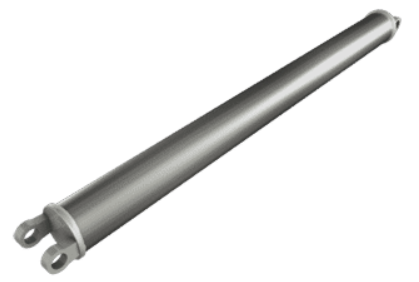
Types of Driveshaft Tubes
One-piece Driveshaft Tube
Extends uninterrupted from the transmission to the differential.
Can be made from steel, aluminum, or composite materials.
Rotates at high speeds, which can create vibration and noise.
Balance weights are attached to reduce vibration and ensure smooth operation.
U-joints connect each end of the driveshaft, allowing power transfer while accommodating chassis movement over rough terrain.
A slip yoke allows the driveshaft to slide in and out, compensating for changes in distance between the transmission and the drive axle during suspension travel.
Two-piece Driveshaft Tube
The two-piece driveshaft consists of two driveshafts connected in the center with bearings and sometimes a constant velocity (CV) joint.
This design is used when the distance between the transmission and drive axle is too long for a single driveshaft.
A U-joint is typically installed at each end of the driveshaft to accommodate vehicle movement.
A slip yoke allows the driveshaft to move in and out, adjusting for changes in distance between the transmission and drive axle.
Often, a two-piece driveshaft has two slip yokes—one at the transmission and one at the center support bearing—to manage the changing relative distance between all three components during travel.