Turbine Quiz
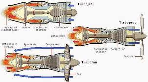
Engine types:
Turbo Prop (drives blade) , Turbo shaft (drives rotor blade)
Turbofan , Turbojet = Thrust; Extraust minimum amount of energy possible
hp producing
Engine providing hp/mechanical energy to do something else
cold and slow energy
spin the compressor extract energy maximum
Turbojet
straight through air flow
small air mass = large acceleration
multiple spools
low speed = low thrust
high TSFC (thrust specific fuel consumption) @ low altitude
poor acceleration
work better at high altitude and harder you run them
ram pressure
simple, light design
Turbofan
bypass airflow
bypass ratio
front fan (most common)
greater propulsive efficiency
better low speed performance
weighs more but fuel efficiency up with power
larger engine diameter
reduced noise
Turboprop
GTE + propeller
Configurations: directly connected, compound compressor, free turbine (gap)
greatest propulsive efficiency
low speed
limit cruise speed, good fuel efficiency
propeller
complicated
reverse thrust
short haul, good for short distances
Turboshaft
similar to turboprop
helicopters
auxiliary power units
Cold Section
Spooled up- running at high, max rpm, full speed, thrust
Unspooled- low rpm, low thrust, 50-?%, idle speed
Compressor Types
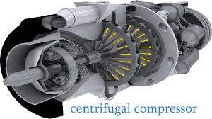
Centrifugal- accelerates air, adds velocity
only need one
compressors do not add pressure to the air
piston compresses the air
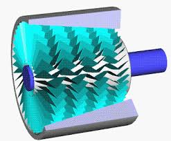
Axial
air flowing front to back
reduce volume, higher density
Hybrid- combination of axial and centrifugal
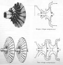
Centrifugal Compressors
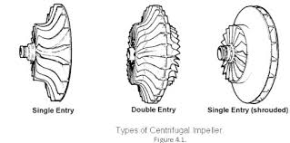
Single Entry- comes in one area
Double Entry- twice amount of air, same amount of metal ( does not increase pressure), highest air flow
Two Stage-
Centrifugal Advantages
simple and robust (harder to brake, hard to fail)
less foreign object damage (FOD)
Centrifugal Disadvantages
lower compression ratio, burning more fuel per hp
(turboshaft and turboprop cheaper)
Impeller
rotates at fast speed, air drawn in
centrifical force throws it through
adds a lot of kinetic energy
increase velocity, decrease static pressure- Bernoulli
more efficient at higher speeds
*Absolute highest pressure is the outlet of the diffuser
velocity slow down, then increase pressure (bc volume expanded)
ex: 2 car lane > 4 lane > 8 lane
Construction
no oil needed bc parts not touching
Clearance (small)
Swirl vanes
Materials- cast metal
Operational theory
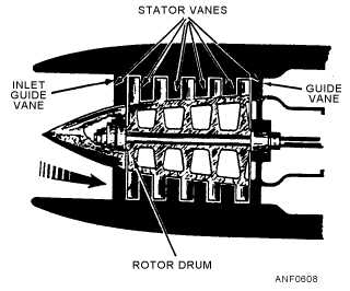
Compressor- major Components
1) Rotating blades 2) Stators
3) Inlet guide vanes
Operational Theory Axial
Pressure rise - 1.2
tapered rotor (look at notes for image)
Axial Advantages
high compression ratio, 20-1
high mass air flow
output determined by how much fuel goes in
air goes all the way through
Axial Disadvantages
complex and expensive
FOD
(Cold section is still hot but called cold cuz less “hot” than the exhaust section)
Blade Stall- air hits it at wrong angle, AOA is incorrect, speed of the air coming in speed of blade can effect it
Hot Section
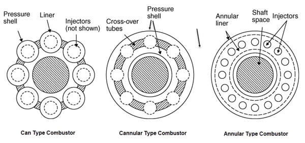
Combustion Chambers
3 types- 1) Can 2) Annular 3) Can-annular
Can- can with flame, old style
able to control each can separately
Annular- the style used today
reverse flow
Can-annular- a bunch of cans connected together
Operation-
Fuel- stable and efficient combustion
“provide stable and efficient combustion over wide variety in operating conditions
if faster, more fuel
(airflow before we have fuel) so we don’t explode
airflow, holes in chamber regulating airflow
secondary nozzle in to the sides
primary nozzle straight through
Ignition- needed at start, during rain, clouds, icing
Velocity- airflow, slower than 80 ft/second so it doesn’t carry fuel all the way down
Quantity- 25% of air coming in used as combustion
turbulent air supports combustor
Combustor Operation
Primary air- burned
Secondary air- used for cooling
*both go through the core of the engine
bypass air- does not go through engine
Can Type Combustors
individual cans
every can has own fuel nozzle
not an ignitor in every can
small diameter
flame works best at low velocities
Can-annular Combustor
can liners
annular housing
primary air in, flame tub, also has holes for secondary air
Annular Type Combustor
single chamber
flame tube not needed (anything modern)
less complex, heat everywhere
more compact engine
hard to repair
Reverse slow
reduced size (length of the engine)
annular design
Turbines: Hot Section
1800 degrees F
2/3 or ¾ being extracted to spin compressor
100,000 hp
bypass air providing thrust?
larger bypass air, larger core energy being extracted by turbine
Basic Configurations
single spool
*multiple spool
internal cooling with bleed air using vanes and stators
vanes like intercooler
(nozzle) guide vanes- direct air to hit turbine at correct angle and velocity
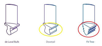
turbine rotor- fir tree
two functions: energy change, direct flow, opposite of compressors
stator vanes trying to increase velocity
get air flowing fastest
impinge on turbine blades at correct angle
(turbine all look like axial flux but not) (not any centri flow turbines)
Area Critical
area of the nozzle, gap between two vanes
compress too much, flames out front
backup in compressor not as much flow, stall
gas velocity at or near speed of sound
constant state (fixed vanes)
Turbine Blades
Impulse: bucket, direction change, newton 3rd law
velocity (may not see drastic change) and directional change
maximum velocity gas flow
Reactive
Reactive-Impulse


Reaction Turbines
acceleration of gases
bernoulli
high velocity gas flow
velocity²
faster air flow, more rotational lift
fast, but not as fast as impulse
blades could stall, shock waves
Impulse-Reaction
reaction- tip (moves faster)
transition (middle of blade)
impulse- root
allows maximum efficiency
Blade Creep- Construction
blade strength
bore scopes (long tube, you can look in, camera has rulers)
Creep- When blade materials are exposed to high stresses lower than the materials' yield strength, they tend to move or get permanent deformation
Construction
Cooling:
compressor bleed air
ceramic coating
not and rotational force, expands
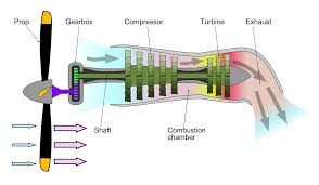
Engine Types:
Turbo Prop: Consists of a gas turbine engine (GTE) driving a propeller. The engine produces power through a combination of gas energy and mechanical energy, resulting in high propulsive efficiency, particularly at low speeds. Some configurations include direct connection to the propeller, a compound compressor setup, and a free turbine arrangement. While it exhibits good fuel efficiency and is ideal for short-haul flights, its complexity can increase with the requirement for reverse thrust capabilities.
Turbo Shaft: Primarily used in helicopters and auxiliary power units. Similar in operation to turboprop engines, they are designed to provide power to a rotor rather than translating that power into forward thrust. They have high power-to-weight ratios and are optimized for the variable power demands of helicopter flight.
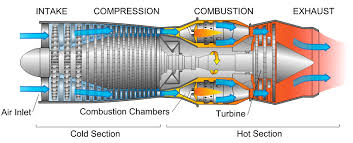
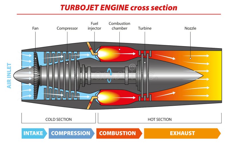
Turbojet
Characteristics: Features a straight-through airflow design enabling a small air mass to achieve large acceleration. Typically includes multiple spool configurations that help optimize performance at various speeds.
Performance: It delivers low thrust at low speeds but significantly improves at high altitudes, characterized by high thrust-specific fuel consumption (TSFC) at lower altitudes and poor low-speed performance.
Design: Simple and lightweight, turbojets are able to create high-speed airflow through the engine, benefiting from ram pressure for additional thrust.
Turbofan
Design Functionality: Utilizes a bypass airflow with a front fan that enhances propulsive efficiency and provides better performance at low speeds compared to turbojets. The bypass ratio is a key factor that defines the ratio of mass airflow bypassing the core engine compared to the airflow through the core.
Advantages: While these engines typically weigh more, their increased fuel efficiency offsets this disadvantage, making them a preferred choice for larger aircraft. They also produce less noise due to design features aimed at reducing the noise footprint.
Turboprop
Efficiency: Known for achieving the greatest propulsive efficiency at low speeds, ideal for short-haul flights. The turboprop engine’s propeller can be adjusted for reverse thrust, enhancing ground maneuverability.
Limitations: While they excel in fuel efficiency, their cruise speeds are limited compared to pure jet engines.
Cold Section
Operating States: Engines can operate in 'spooled-up' states at maximum RPM, providing full thrust, or in 'unspooled' states where they operate at idle, exhibiting low thrust levels.
Compressor Types
Centrifugal Compressors: These compressors accelerate air and add velocity but do not increase pressure significantly, allowing for a simple and robust design that is less prone to foreign object damage (FOD). They are ideal for smaller engines requiring lower compression ratios.
Axial Compressors: Deploy a design where air flows front to back, reducing volume and increasing density. They achieve high compression ratios, approximately 20:1, and are highly efficient with a high mass airflow but can be complex and expensive.
Hot Section
Combustion Chambers: Types include can, annular, and can-annular configurations, each offering different operational efficiencies and complexity.
Combustor Operation: It is crucial to maintain stable and efficient combustion across a wide range of operating conditions. Proper airflow management is critical to prevent combustion instability and ensure optimal operational efficiency.
Turbines and Basic Configurations
Turbine Performance: At high temperatures, often near 1800 degrees Fahrenheit, turbines extract energy to spin the compressors.
Blade Design: Turbine blades are designed considering impulse and reaction forces to maximize efficiency and performance. Creep, which is the permanent deformation of blade materials under high-stress conditions, is a significant factor in the longevity and efficiency of turbine operations. Blade cooling technologies and coatings are utilized to manage extreme operational temperatures and stresses.
This comprehensive overview highlights the intricacies and operational dynamics of various engine types, their configurations, and overall performance characteristics essential for understanding modern aviation propulsion systems.
Engine Types Overview
Turbo Prop Engine: Consists of a gas turbine engine (GTE) driving a propeller. This engine type produces power through a convergence of gas energy and mechanical energy, resulting in exceptional propulsive efficiency, especially at low speeds. Major configurations include:
Directly Connected: Engine and propeller are directly linked for optimal efficiency.
Compound Compressor: Combines multiple stages to enhance efficiency.
Free Turbine Arrangement: Allows for independent operation of the turbine from the propeller, enhancing performance.
Uses: Ideal for regional aircraft and short-haul flights due to its efficiency; the capability of reverse thrust also assists ground maneuverability. The complexity increases with reverse thrust requirements.
Turbo Shaft Engine: Primarily employed in helicopters and auxiliary power units. While similar in operation to turboprop engines, turbo shafts focus on providing power for rotational motion rather than translational thrust. Key features include:
High Power-to-Weight Ratio: Effectively meets the variable power demands of rotorcraft.
Optimized for Variable Power Demands: Engine performance adapts rapidly to helicopter flight conditions.
Turbojet Engine: Features a straight-through airflow design that permits a small air mass to achieve remarkable acceleration. Its notable performance characteristics are:
Low Thrust at Low Speeds: Struggles with acceleration but performs excellently at high altitudes, achieving significant thrust.
High Thrust-Specific Fuel Consumption (TSFC): Particularly at lower altitudes, highlighting inefficiencies in fuel use during takeoff and landing.
Simple and Lightweight Design: Turbojets capitalize on ram pressure for thrust enhancement, suited for high-speed applications.
Turbofan Engine: Incorporates a bypass airflow with a front fan that significantly enhances propulsive efficiency. Distinction lies in:
Bypass Ratio: Determines the mass airflow bypassing the core engine relative to that through the core, significantly influencing performance.
Better Low-Speed Performance: Compared to turbojets, making them preferable in commercial aviation despite their increased weight.
Reduced Noise Levels: Utilizes design features aimed at minimizing noise output, vital for commercial flight operations.
Engine Sections
Cold Section: Refers to operational states of engines during their spooled-up (maximum RPM, full thrust) and unspooled (idle, low thrust) states. Critical components include:
Compressor Types:
Centrifugal Compressors: Simple design, accelerates air but won’t significantly raise pressure; ideal for smaller applications due to robust characteristics and low susceptibility to foreign object damage (FOD).
Axial Compressors: More complex, featuring air flowing from front to back; can achieve high compression ratios of up to 20:1, contributing to overall engine efficiency but often at a higher cost.
Hot Section: Involves components facing high temperature and pressure during operation:
Combustion Chambers: Encompasses three types: can, annular, and can-annular, each providing varying operational efficiencies.
Ignition and Combustion Management: Effective combustion requires stable airflow management to prevent instability and ensure combustion efficiency over diverse conditions.
Blade Design and Cooling Technologies: Focuses on managing the extreme temperatures experienced, ensuring longevity while maximizing efficiency in turbine performance.
Turbines: Hot Section Dynamics
Energy Extraction: Turbines operate at high temperatures (close to 1800°F), extracting energy to power compressors effectively. Understanding turbine configurations:
Impulse and Reactive Types: Designs focus on the acceleration of gases to maximize efficiency while managing the risk of stall due to shock waves at high speeds.
Blade Cooling Techniques: Implemented to manage stress and temperature, ensuring material integrity over prolonged operational periods. This includes cooling air methods and advanced material coatings.
This comprehensive overview captures the intricacies of aeronautical engines and their operational dynamics, offering insights into various types and their configurations crucial to modern aviation propulsion systems.
Engine Types Overview
Turbo Prop Engine
Consists of a gas turbine engine (GTE) driving a propeller. This engine type produces power through a convergence of gas energy and mechanical energy, resulting in exceptional propulsive efficiency, especially at low speeds. Major configurations include:
Directly Connected: Engine and propeller are directly linked to maximize efficiency during operation.
Compound Compressor: Combines multiple stages of compression to enhance total efficiency and performance across varying speeds.
Free Turbine Arrangement: Allows for independent operation of the turbine from the propeller, meaning the turbine can operate at optimal speeds regardless of the propeller's speed, further enhancing fuel efficiency and overall performance.
Applications: Ideal for regional aircraft and short-haul flights due to its high fuel efficiency and flexibility. The capability of reverse thrust aids in ground maneuverability, particularly for takeoffs and landings in confined spaces.
Turbo Shaft Engine
Primarily employed in helicopters and auxiliary power units, turbo shaft engines are similar in operation to turboprop engines but are specifically designed to provide power for rotational motion rather than translational thrust. Key features include:
High Power-to-Weight Ratio: Packed with performance that meets the variable power demands of rotorcraft, ensuring robust lift capabilities even in challenging flight conditions.
Optimized for Variable Power Demands: Turbo shafts can adjust rapidly to fluctuating power requirements during flight maneuvers, offering essential support in helicopter operations that require agility and responsiveness.
Usage: Widely used in military and civilian helicopters, as well as in ground vehicles where auxiliary power is required.
Turbojet Engine
Features a straight-through airflow design enabling a small air mass to achieve remarkable acceleration. Its notable performance characteristics are:
Low Thrust at Low Speeds: While turbojets may struggle with acceleration and achieving low-speed thrust, their performance significantly improves at high altitudes, where they benefit from thinner air and can maintain a high speed.
High Thrust-Specific Fuel Consumption (TSFC): Particularly at lower altitudes, turbojets showcase inefficiencies in fuel use during takeoff and landing, leading to a high operational cost in those phases.
Simple and Lightweight Design: Turbojets capitalize on ram pressure for thrust enhancement, making them well-suited for high-speed applications such as military fighter jets and supersonic transports.
Turbofan Engine
Incorporates a bypass airflow with a front fan that significantly enhances propulsive efficiency. Key differentiators:
Bypass Ratio: Determines the mass airflow that bypasses the core engine relative to that passing through the core, crucial for performance metrics; higher bypass ratios generally lead to better efficiency and lower noise output.
Enhanced Low-Speed Performance: Compared to turbojets, turbofans provide improved thrust at lower speeds, making them the preferred engine type for commercial aviation applications.
Reduced Noise Levels: Design features, including sound-dampening technologies, minimize noise output, which is imperative for commercial flight operations, especially when flying over populated areas.
Engine Sections
Cold Section
Refers to operational states of engines during their spooled-up (maximum RPM, full thrust) and unspooled (idle, low thrust) stages. Critical components include:
Compressor Types:
Centrifugal Compressors: Simple designs that accelerate air but do not significantly raise pressure, making them ideal for smaller applications due to their robust characteristics and low susceptibility to foreign object damage (FOD).
Axial Compressors: More complex designs featuring air flowing from front to back, which can achieve high compression ratios of up to 20:1, significantly contributing to the overall efficiency of the engine yet often at higher production and maintenance costs.
Hot Section
Involves components that face extreme temperature and pressure during operation:
Combustion Chambers: Comprising three types: can, annular, and can-annular, each offering different operational efficiencies and complexities based on the required performance and design specifications.
Ignition and Combustion Management: Effective combustion requires stable airflow management to prevent instability and ensure optimal combustion efficiency over diverse conditions; includes various advanced ignition techniques that ensure reliable starts across varying environmental conditions.
Blade Design and Cooling Technologies: Focuses on managing the extreme temperatures encountered, utilizing advanced cooling strategies to ensure longevity while maximizing turbine performance efficiency.
Turbines: Hot Section Dynamics
Turbines typically operate at high temperatures (close to 1800°F), extracting energy to power compressors effectively. Understanding turbine configurations is essential:
Impulse and Reactive Types: Turbines differ in their design focus, with impulse turbines generating thrust through directional changes and reactive turbines enhancing efficiency by leveraging acceleration of gases, impacting overall engine performance.
Blade Cooling Techniques: Various methodologies, such as the utilization of compressor bleed air and modern materials, are implemented to manage temperature stresses, ensuring the materials can withstand extreme operational conditions without compromising engine integrity.
This comprehensive overview captures the intricacies of aeronautical engines and their operational dynamics, offering insights into various types and their configurations crucial to modern aviation propulsion systems.