PO 1.9 Prefab Parametric
Parametric Design
“In parametric design, it is the parameters of a particular design that are declared, not its shape…Equations/Rules can be used to describe relationships between objects, thus defining an associative geometry.” - Branko Kolarevic
“Parametric expressions, therefore, allow users to change the values of key parameters, and to observe the propagation of changes on dependent expressions, and hence upon the dependent geometry. This is often referred to as strategic manipulation.” - Peter Szalapaj
The relationship between the three-dimensional digital models and the built environment it is based upon is the output information between the computer and the automated fabrication devices. This output is achieved through digital code and is referred to as CNC or computer numerical control.
The use of digital fabrication techniques in architecture allows for greater diversity in building form, detail, and proportion. Advocates for digital design argue that these fabrication techniques provide a combination of creative solutions achieved at a similar efficiency to mass-production. It is argued that the digital fabrication overcomes the repititiousness of modernity without a loss of productivity. This process is often referred to as “mass-customization”.
Make Magazine

Magazine about parametrics
covers projects, stories, and new technologies
Methods of Modification
Additive Processes
Subtractive Processes
Bending Processes
SLA
Stereolithography Apparatus
Layers of liquid metal hardened by UV light
3D Printing Process
SLS
Selective Laser Sintering
Uses a laser to sinter powder based materials together, layer-by-layer, to form a solid model
3D Printing Process
FDM
Fused Deposition Modeling
Molten thermoplastic is extruded through a nozzle to build objects layer-by-layer
3D Printing Process
The Porter House
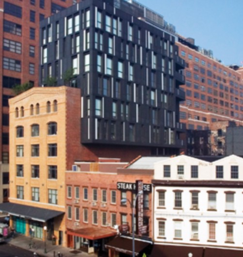
2003, New York
Renovation and conversion of a 6-story 30,000 sq. ft. warehouse into residential condominiums
Gregg A. Pasquarelli - SHoP Architects
A new 20,000 sq. ft. addition added 4 stories to the existing building and an 8-foot cantilever on the south facade
There’s a shared boundary between the original Renaissance Revival facade and the new addition
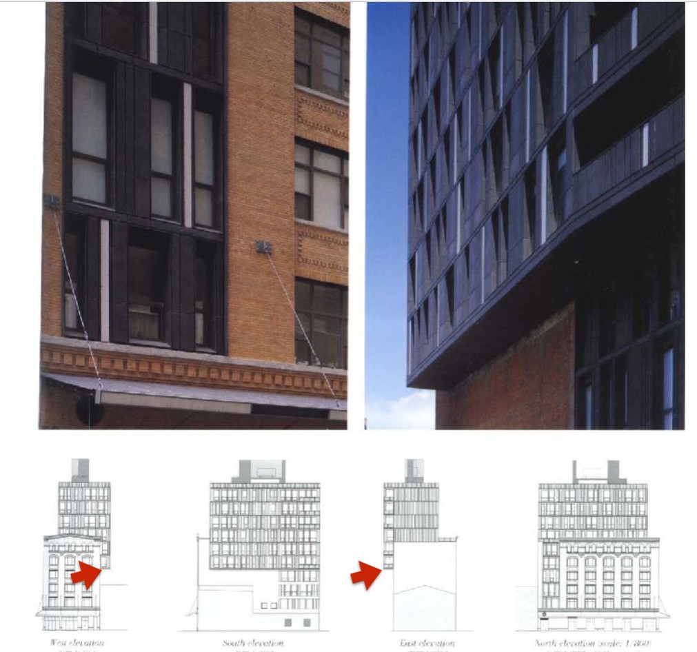
Custom zinc panel system for the facade and floor-to-ceiling windows in the new addition
Metal framework of the addition is clad in ANTHRA-ZINC
Custom-designed, laser-etched zinc metal wall panel cladding system
Zinc rain-screen emerges from a family of 15 profile types, from which there are 150 different profile versions, yielding 4,000 total panels
Variations achieved by cutting and bending each profile panel type differently
Creators were going for an ambience of complexity and randomness, to fit in with the existing environment
The use of BIM achieved huge gains in fabrication and installation times
Elevation pattern based on the most efficient layout of panels on a standard width of sheet metal
Accuracy in the production of the varying panel elements and efficiency of material use
Standard zinc sheets of 39”x118”
Program team worked closely with the material fabricator to minimize material waste
Software was standard to the sheet metal industry
Panels were folded and cut directly according to the SHoP digital files
Highly customizable look with various panel sizes
Vertical light boxes draw pedestrian eyes upward and give a sense of lightness to the addition, especially at night
3,800 piece jigsaw puzzle
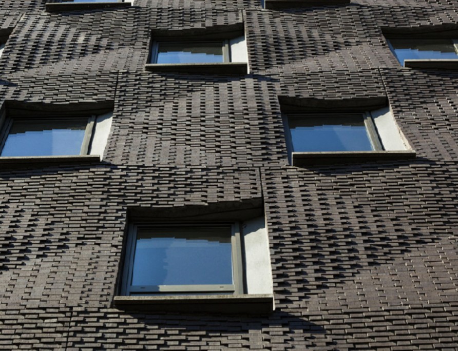
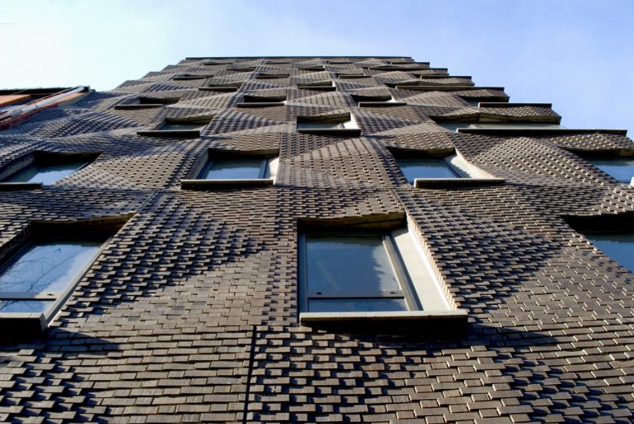
Mulberry House
Nolita District, New York, 2008
9 residential condos
Required a primarily brick exterior to match the neighborhood
Typical brick construction using masonry veneers and ties
Precast system
Uses a Flemish Bond layout
Elevation geometry is in multiples of brick dimensions
Precasting saves labor costs and time on site
Each brick is offset 3/4” from its adjacent brick
Grid of 6 squares in a 3:2 proportion
Everything along the facade conforms to this proportional pattern
Low to high to medium points
Produce undulation and visual interest
Pattern breaks down into 8 different precast elements, each being a portion of the overall geometry
Staggered pattern of alternating elements
Addition of a tapered vertical fin to the window opening and sill above
Precast building ends up being much more complex than a simple precast element
Mulberry House Prefabrication
Each precast element created from a mold
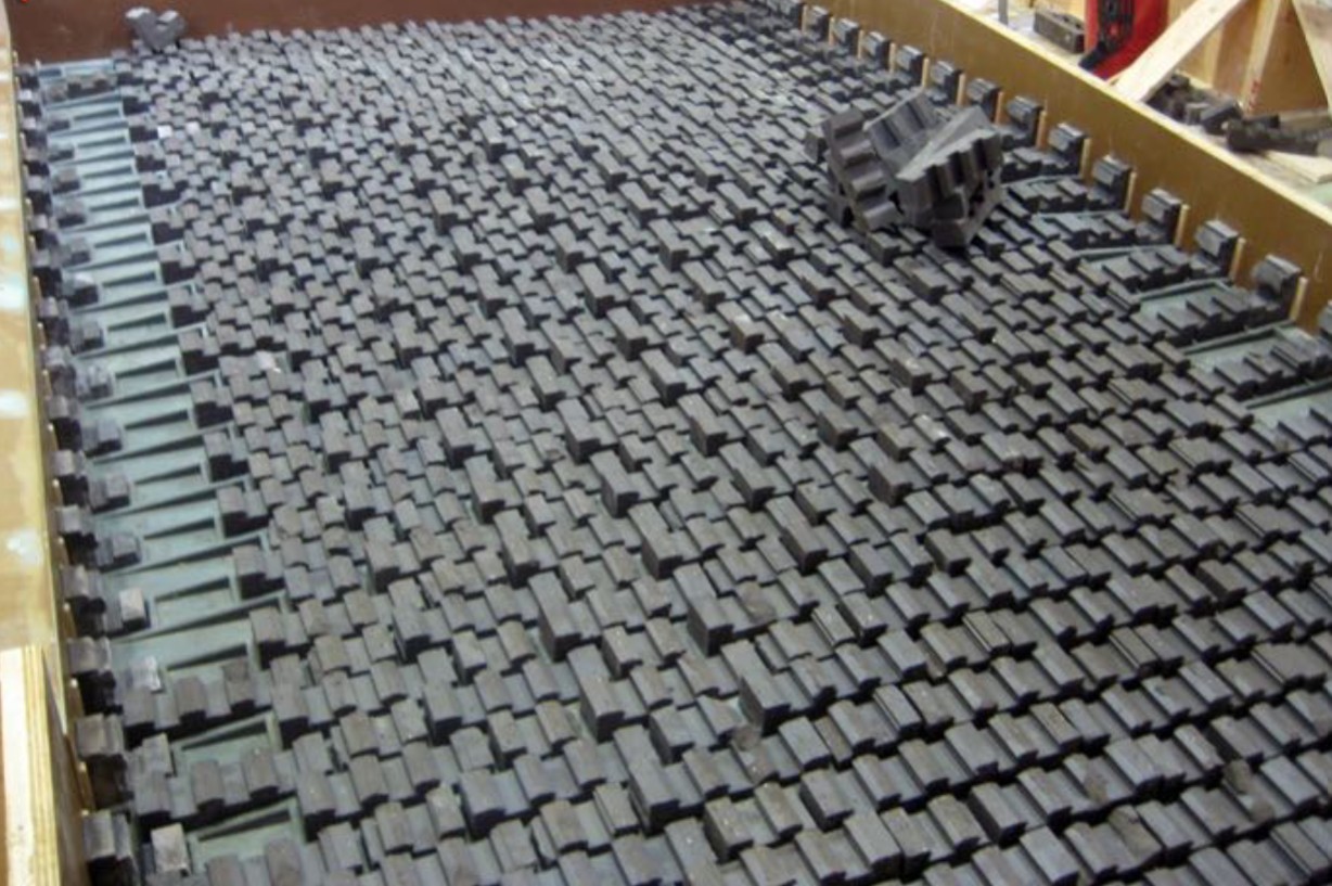
Special bricks are designed to be held in the mold and cast into concrete panels, with anchors on the inside face
Molds arranged so that the corners look like full bricks
Maintains a Flemish Bond
Concrete poured to the mold’s brim
Concrete sets between the anchors of the brick veneers
Mold designed through digital fabrication and CNC routed
Synthetic mold surface positions the brick and releases the precast concrete without adhesion
Allows concrete to get between the bricks and create a visual false mortar
Tapered section is a mold extension, allows the accomplishment of the adjacent fin
Sill is more complicated as the protrusion beyond the precast face makes it extremely difficult to include in the mold
Sill is molded separately and bonded to the precast element after it has been removed from the mold
There is no indication line of the sill addition in the assembly process documents
There are voids in the mold to reduce the overall weight of these hanging concrete pieces
Steel anchors are embedded into the precast concrete to attach the facade pieces to the building
Prefabricated pieces are eventually lifted and attached to the building, resulting in the rippling facade
Gaps between pieces express the construction process by slightly revealing the prefabricated individual pieces
Maximum undulation and minimum weight to concrete