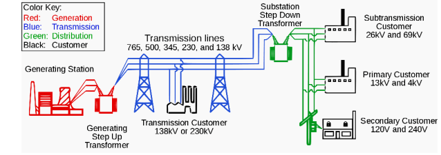
Distribution
Electric Power Distribution
Final Stage in the delivery of electric power
Carries Electricity from transmission system to individual consumer
Distribution System
All facilities and equipment connecting a transmission system to consumer’s equipment
Distribute electrical energy
Sequential flow of procedures, system, and activities which are designed and linked to facilitate and monitor the movement of goods and services from the source to the consumer
Measured in the Distribution System during Normal Conditions
Quality of voltage
frequency
resulting current
Primary Metering
direct to primary voltage
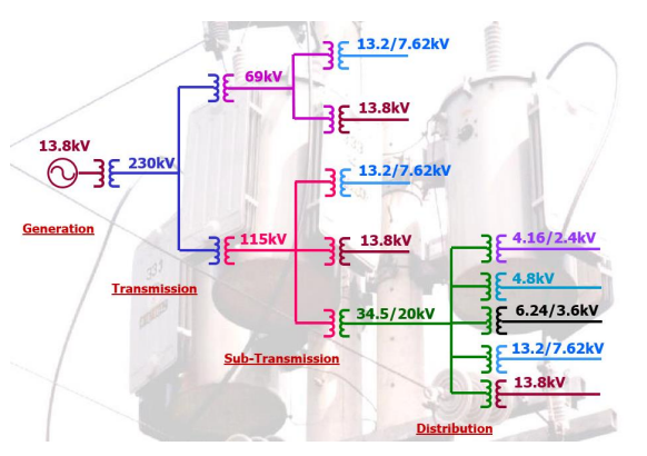
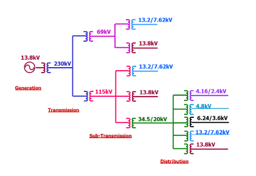
Primary Nominal Voltage
13.2kV 13.8kV 24.5kV 69kV 115 kV
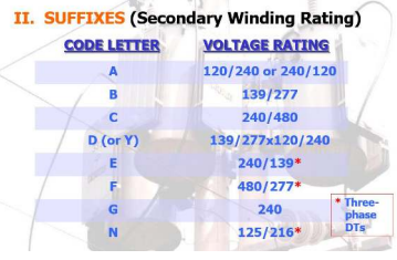
Secondary Nominal Voltage
230V 400V 460 V
Power Quality
knowing the characteristics of the distribution utility, its capabilities, and limitations
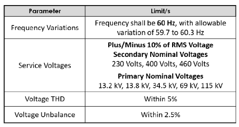
Voltage THD - Voltage Total Harmonic Distortion
Voltage Unbalance
Ave - low value / ave x 100
Voltage Mismatch
di tugma ang supply sa equipment
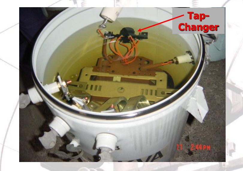
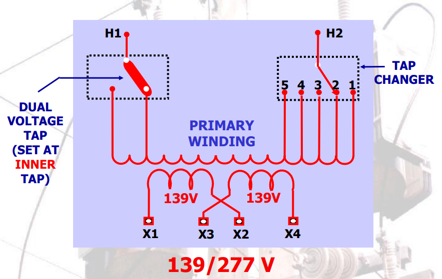
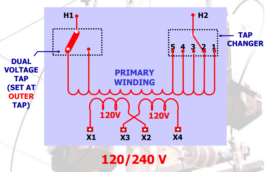
Tap Setting
increase by 2.5%
up to 5 tap only
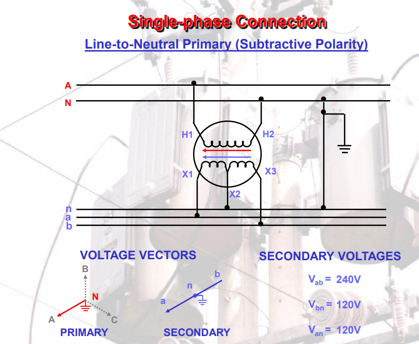
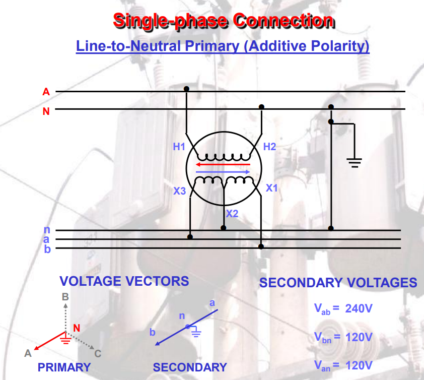
LINE TO NEUTRAL - PHASE VOLTAGE
NEUTRAL - PASSAGEWAY
GROUND - RETURN TO EARTH
TRIPLEX ALL ALUMINUM CONDUCTOR 3/O
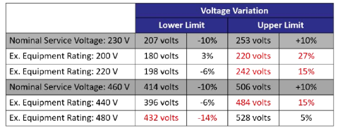
Effect of Utility Variations on Equipment Ratings
Must operate satisfactorily within the -10% to +10% voltage variation
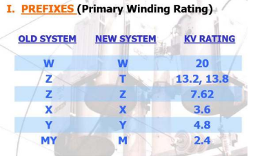
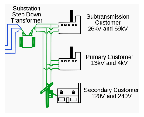
Primary Voltages
large consumers are fed directly from distribution voltages
utility customers are connected to a transformer that reduces the distribution voltage to the low voltage "utilization voltage", "supply voltage" or "mains voltage" used by lighting and interior wiring systems.
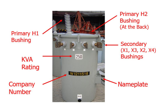
Transformer
Passive electrical device that transfers electrical energy from one electrical circuit to another, or multiple circuits.
Primary winding of a transformer is connected to the input voltage supply and converts or transforms the electrical power into a magnetic field.
Electrical device that uses electromagnetic induction to pass an alternating current (AC) signal from one electric circuit to another, often changing (or "transforming") the voltage and electric current.
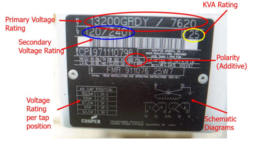
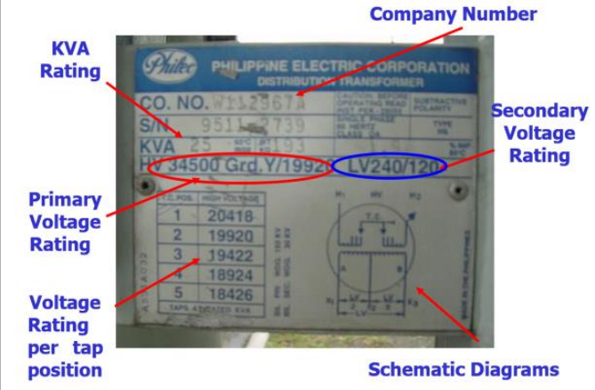
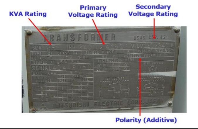
SYMBOLS USED IN TRANSFORMER VOLTAGE RATINGS
Dash (-)
separate the voltage rating or ratings of separate windings.
34500 Grd. Y / 19920 V – 240 / 120 V
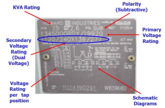
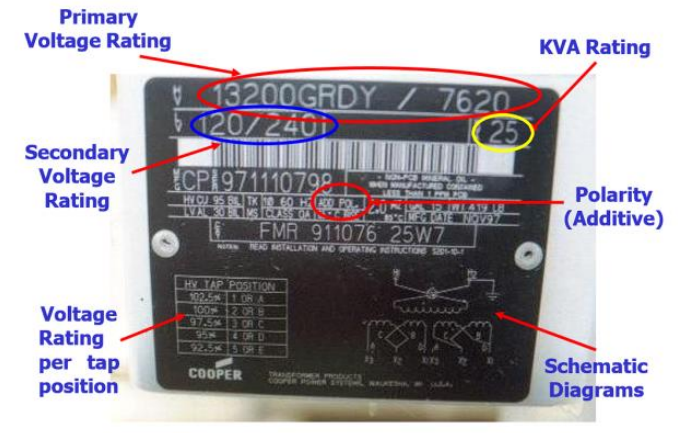
Slant or Slash (/)
separate voltage to be applied or to be obtained from the same winding.
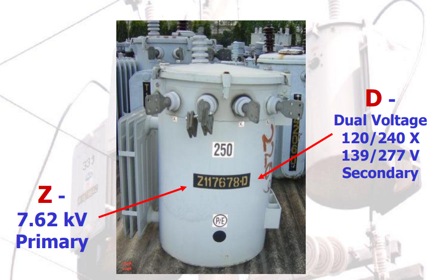
13200 GRDY / 7620 V – 120 / 240 V
Cross (X)
separate voltages which can be obtained by reconnecting the coils of a winding in series or multiple combinations.
34500 Grd. Y / 19920 V – 240 / 120 V X 139 / 277 V
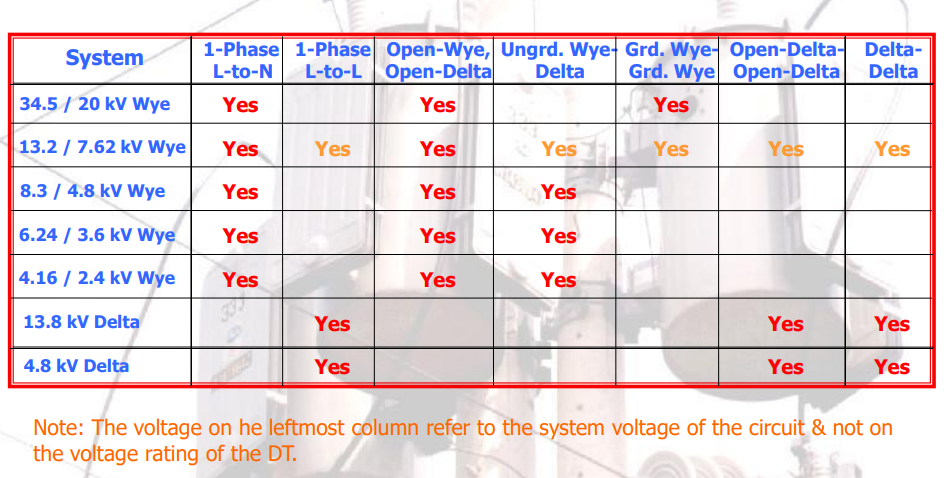
PRIMARY VOLTAGE RATING COMMONLY USE
34500Grd. Y / 19920
Single-bushing DTs for line-to-ground connections on effectively grounded systems with line-to-line voltages of 34.5kV.
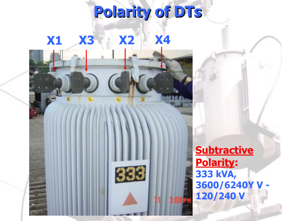
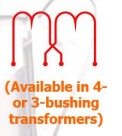
3600 / 6240Y
Two-bushing DTs for line-to-ground connection on system with line-to-line voltages of 6.24kV.
2400 / 4160Y
Two-bushing DTs for line-to-ground connection on system with line-to-line voltages of 4.16kV.
4800 / 8300Y
Two-bushing DTs for line-to-ground connection on system with line-to-line voltages of 8.3kV or for line-to-line connection on system with line-to-line voltage of 4.8kV.
13200
for line-to-line connection on system of 13.2kV line-to-line.
13200Grd.Y / 7620
Single-bushing DTs for line-to-ground connection on effectively grounded systems with line-to-line voltages of 13.2kV.
7620 / 13200Y
Two-bushing DTs for line-to-ground connection on system with line-to-line voltages of 13.2kV
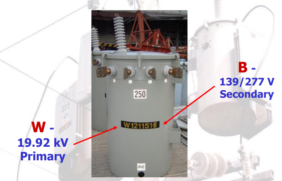
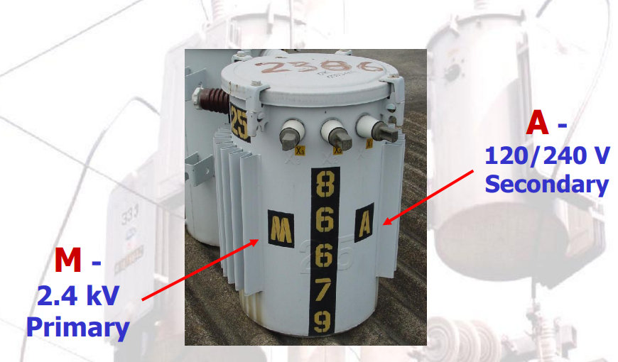
DT NUMBER CODING SYSTEM OF MERALCO
DIFFERENCE BETWEEN 120/240- & 240/120-VOLTRATINGS
120/240
2 Section secondary winding which can be connected in parallel for output voltage 120V, in series for output voltage 240V, or in series for 3-wire service for 120/240V output voltage.
120V (2) = 240V
240/120
Mid-tapped secondary suitable for 2-wire service at voltage 240V, or for 3-wire service. Cannot be connected for 2-wire service at voltage 120V.
240V/2 = 120V

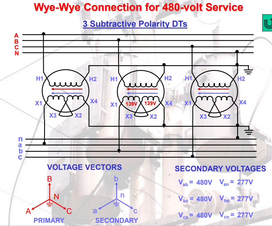
Secondary Voltage
provided by distribution transformers that are connected to the primary system, which are usually associated with utilization voltages.
Electrical Load
consumes electric power such as appliances
converts electricity into other energy such as heat, light, motion etc.
Nature of Load
Resistive load
Obstruct the flow of electricity
consist of a coil and winding made up of copper or aluminum
produces magnetic field
Include any type of heating element
Inductive load
stores energy in the form of a magnetic field
current lags behind the supply voltage
lagging power factor
provide power to electric motor
Capacitive load
stores electrical energy in the form of an electrostatic charge
current leads behind the supply voltage
leading power factor
Power System Load
Domestic load
household appliances
usually single phase ac loads
operated by single phase ac supply
either lagging or unity factor
Resistive or inductive loads
Commercial load
business like office
Industrial load
small to large factories and manufacturing
induction motors
composite loads
Agriculture load
use in agriculture works
motor
Electrical Power Plant
Power Station
Generate Electricity
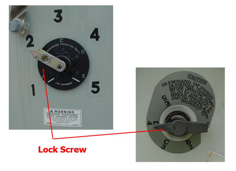
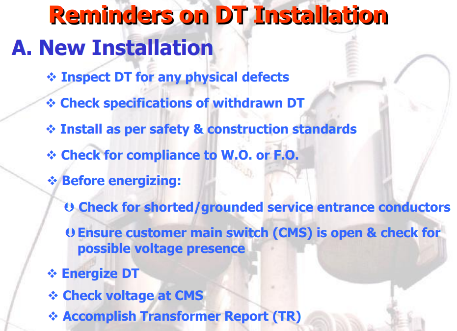
Operation
1. De-energize the DT
2. Loosen lock screw
3. Rotate switch to desired position
4. Tighten lock screw
5. Energize the DT
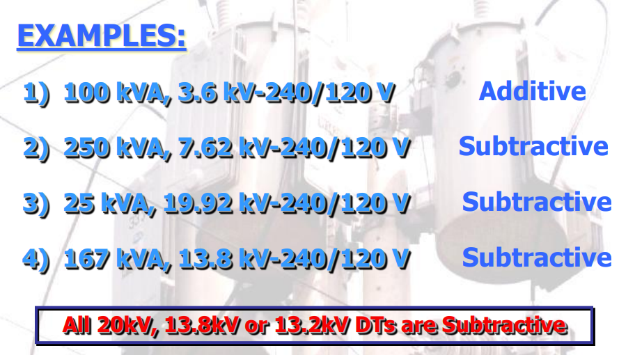
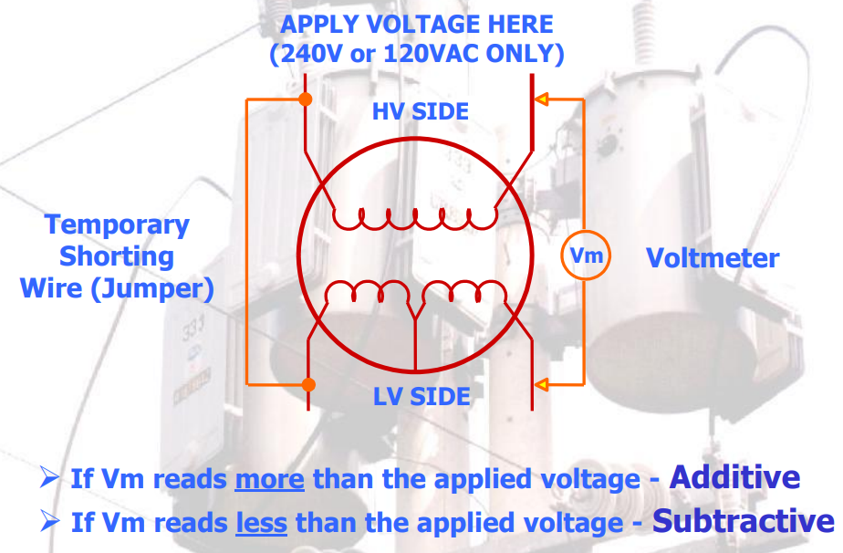
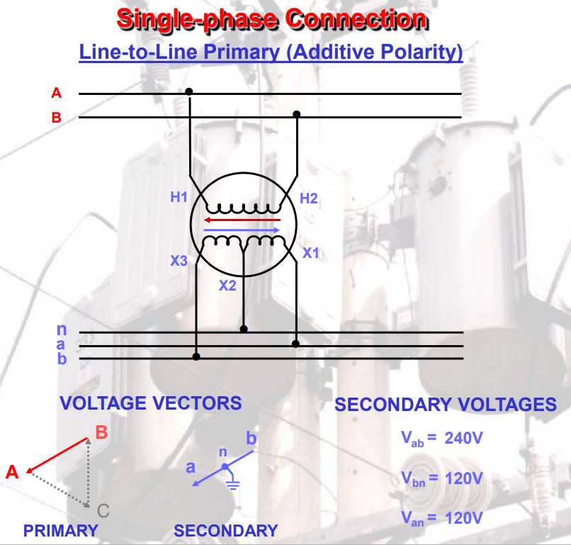
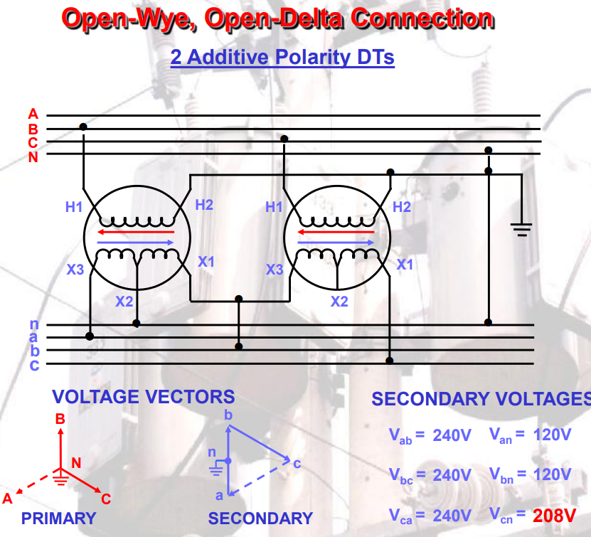
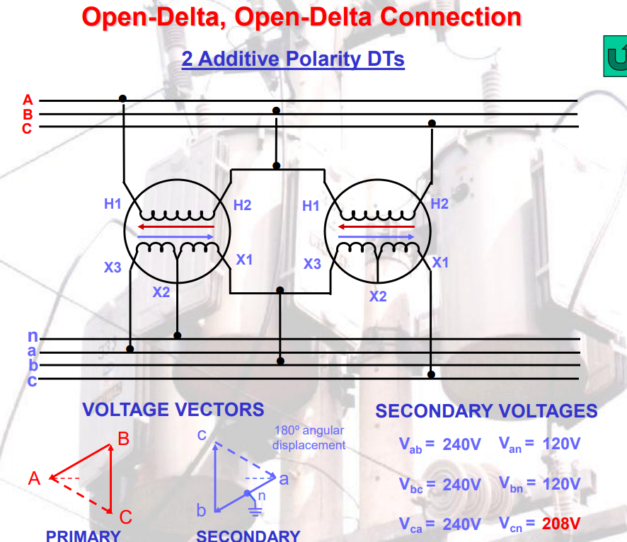
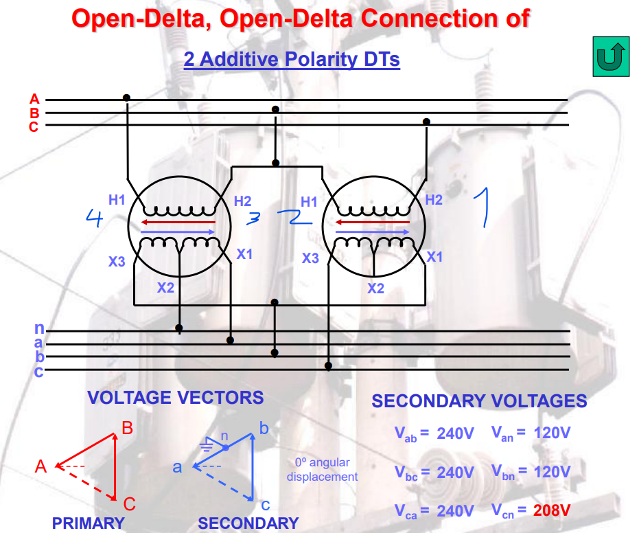
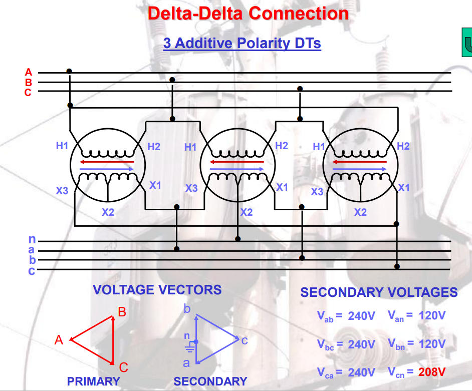
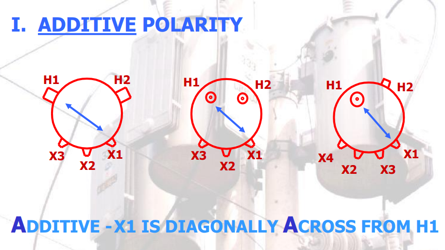
Additive
200kVA or smaller
8.66 kV below
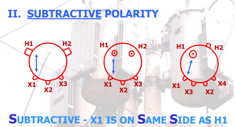
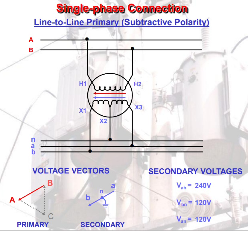
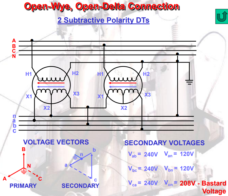
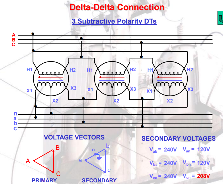
Subtractive
does not meet the criteria