AP Physics C: Unit 3 - RC Circuits Study Guide
AP Physics C: Unit 3 - RC Circuits
Steady-State Behavior of Capacitors
Before diving into the calculus involved in time-dependent circuits, it is crucial to understand how capacitors behave at the extreme time boundaries. These are the most common conceptual questions on the AP exam.
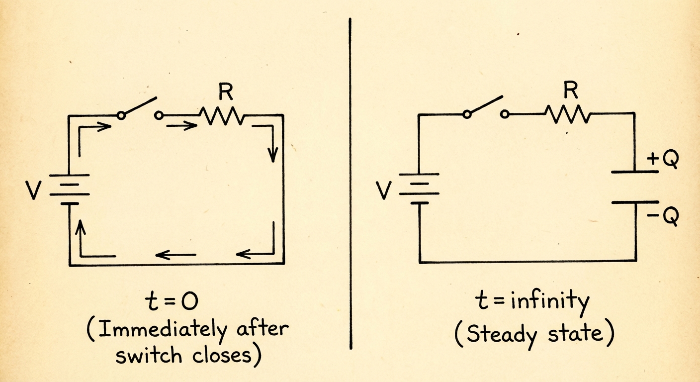
The "Immediately After" State ($t = 0$)
When a switch is first closed in a circuit containing an uncharged capacitor:
- There is no charge accumulation on the plates yet ($q=0$).
- Since the potential difference across a capacitor is $V_C = q/C$, the voltage drop across the capacitor is $0\text{ V}$.
- Key Concept: An uncharged capacitor behaves like a short circuit (ideal wire) with zero resistance.
The "Long Time After" State ($t \to \infty$)
After a switch has been closed for a very long time:
- Current flows until the capacitor is fully charged.
- Once fully charged, the capacitor opposes the EMF of the source such that no more charge can flow onto the plates ($i=0$ in the branch containing the capacitor).
- Key Concept: A fully charged capacitor behaves like an open circuit (a broken wire).
Quantitative Analysis: The Charging RC Circuit
An RC Circuit contains a resistor ($R$) and a capacitor ($C$) in series with an Electromotive Force (EMF, denoted as $\mathcal{E}$). When analyzing the charging phase, we use Kirchhoff's Loop Rule (KVL).
Deriving the Charging Equation
This derivation appears frequently in Free Response Questions (FRQs). You must be able to set up the differential equation.
Apply KVL: moving clockwise through the battery, resistor, and capacitor:
\mathcal{E} - VR - VC = 0
\mathcal{E} - i(t)R - \frac{q(t)}{C} = 0Substitute the Differential Definition: Recall that instantaneous current is the time derivative of charge, $i = \frac{dq}{dt}$:
\mathcal{E} - R\frac{dq}{dt} - \frac{q}{C} = 0Separate Variables: We need to isolate $q$ terms on one side and $t$ terms on the other:
\mathcal{E} - \frac{q}{C} = R\frac{dq}{dt}
\frac{C\mathcal{E} - q}{C} = R\frac{dq}{dt}
\frac{dq}{C\mathcal{E} - q} = \frac{1}{RC} dtIntegrate: Integrate from initial state ($t=0, q=0$) to time $t$ with charge $q(t)$:
\int{0}^{q} \frac{dq}{C\mathcal{E} - q} = \int{0}^{t} \frac{1}{RC} dtSolve for $q(t)$:
-\ln(C\mathcal{E} - q) \Big|_0^q = \frac{t}{RC}
\ln\left(\frac{C\mathcal{E} - q}{C\mathcal{E}}\right) = -\frac{t}{RC}
C\mathcal{E} - q = C\mathcal{E} e^{-t/RC}
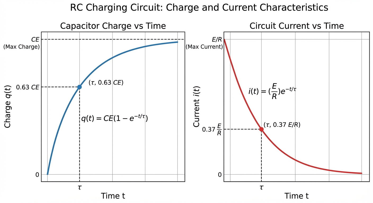
Final Charging Formulas
Charge as a function of time:
q(t) = C\mathcal{E} \left( 1 - e^{-\frac{t}{RC}} \right)
- At $t=0$, $q=0$.
- At $t \to \infty$, $q = C\mathcal{E} = Q_{\text{max}}$.
Current as a function of time:
To get current, take the derivative of charge ($i = \frac{dq}{dt}$):
i(t) = \frac{d}{dt} \left[ C\mathcal{E} (1 - e^{-t/RC}) \right]
i(t) = \frac{\mathcal{E}}{R} e^{-\frac{t}{RC}}
- At $t=0$, $i = \mathcal{E}/R$ (Max current, acts like a wire).
- At $t \to \infty$, $i = 0$ (open circuit).
Quantitative Analysis: The Discharging RC Circuit
Consider a capacitor that is already charged with charge $Q0$ and potential difference $V0$. If the battery is removed and the circuit is closed (just $R$ and $C$ in a loop), the capacitor acts as the energy source.
Deriving the Discharging Equation
Apply KVL:
VC - VR = 0 \implies \frac{q}{C} - iR = 0Crucial Substitution: Because the capacitor is losing charge, the current is defined as the negative rate of change of charge:
i = -\frac{dq}{dt}
(Note: Neglecting this negative sign is a common student error.)Differential Equation:
\frac{q}{C} + R\frac{dq}{dt} = 0
\frac{dq}{q} = -\frac{1}{RC} dtIntegrate and Solve:
\int{Q0}^{q} \frac{dq}{q} = \int{0}^{t} -\frac{1}{RC} dt \ln\left(\frac{q}{Q0}\right) = -\frac{t}{RC}
Final Discharging Formulas
Charge as a function of time:
q(t) = Q_0 e^{-\frac{t}{RC}}
Current as a function of time:
i(t) = -\frac{dq}{dt} = \frac{Q0}{RC} e^{-\frac{t}{RC}} = I0 e^{-\frac{t}{RC}}
(Note: The direction of current flow during discharge is opposite to the charging direction).
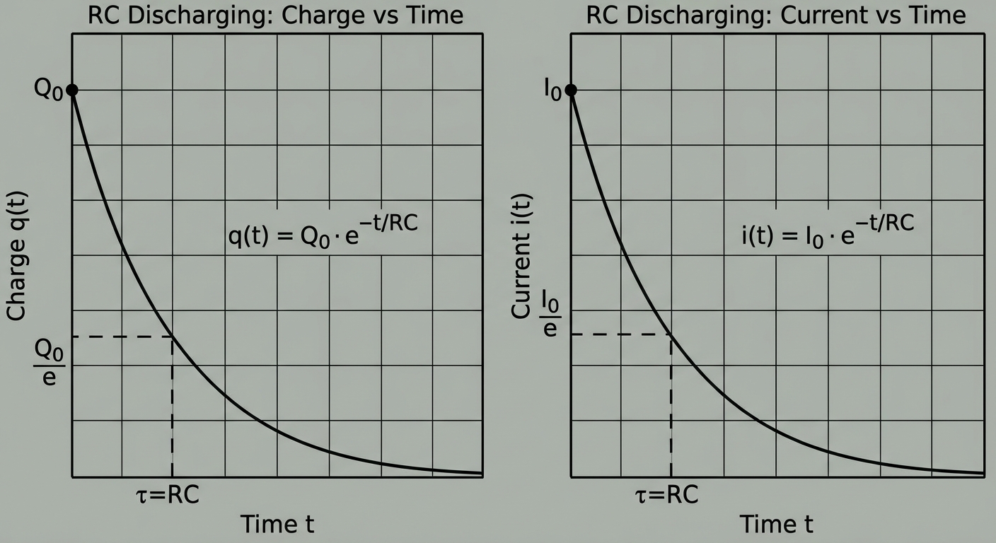
The Time Constant ($\tau$)
The quantity $RC$ appears in all exponents. It is defined as the inductive time constant, $\tau$ (tau).
\tau = R \cdot C
- Units: Ohms ($\Omega$) $\times$ Farads ($F$) = Seconds ($s$).
- Physical Significance: It represents the "sluggishness" of the circuit. A large $\tau$ means the capacitor charges/discharges slowly; a small $\tau$ means it happens quickly.
Useful Benchmarks
- At $t = \tau$ (Charging): The capacitor reaches $(1 - e^{-1}) \approx \mathbf{63.2\%}$ of its max charge.
- At $t = \tau$ (Discharging): The capacitor drops to $e^{-1} \approx \mathbf{36.8\%}$ of its initial charge.
Energy in RC Circuits
The conservation of energy in these circuits is frequently tested.
Energy Balance Equation
For a charging circuit, the work done by the battery is distributed between the resistor (heat) and the capacitor (stored potential energy).
W{\text{battery}} = U{\text{capacitor}} + W_{\text{resistor}}
- Total Work by Battery: $W = Q_{\text{final}}\mathcal{E} = C\mathcal{E}^2$
- Final Energy Stored in Capacitor: $U_C = \frac{1}{2} C\mathcal{E}^2$
- Energy Dissipated by Resistor:
WR = \int{0}^{\infty} i^2(t)R \, dt = \frac{1}{2} C\mathcal{E}^2
Key Insight: In a simple RC charging circuit governed by a constant EMF, exactly half of the energy supplied by the battery is stored in the capacitor, and exactly half is dissipated as heat in the resistor, regardless of the resistance $R$.
Worked Example
Problem: A $1000 \, \mu\text{F}$ capacitor and a $2.0 \, \text{k}\Omega$ resistor are connected in series with a $12 \, \text{V}$ battery.
- What is the time constant?
- What is the current in the circuit at $t = 4.0 \, \text{s}$?
Solution:
Calculate $\tau$:
\tau = RC = (2000 \, \Omega)(1000 \times 10^{-6} \, \text{F}) = 2.0 \, \text{s}Current at $t=4s$:
Usually, charging current follows: $i(t) = \frac{\mathcal{E}}{R} e^{-t/\tau}$
I_{\text{max}} = \frac{12 \, \text{V}}{2000 \, \Omega} = 0.006 \, \text{A} = 6 \, \text{mA}
Since $t=4\text{s}$ is exactly $2\tau$:
i(4) = (6 \, \text{mA}) e^{-4/2} = (6 \, \text{mA}) e^{-2}
i(4) \approx 6(0.135) = 0.81 \, \text{mA}
Common Mistakes & Pitfalls
Confusing $VR$ and $VC$:
- During charging: $VC$ increases exponentially, but $VR$ decreases exponentially. Remember $V_R = iR$, and current drops as the capacitor fills up.
The "Parallel Branch" Trap:
- If a resistor $R2$ is placed in parallel with the capacitor, the steady-state ($t \to \infty$) voltage across the capacitor is NOT the battery EMF. It is the voltage across the parallel resistor $R2$ (determined by voltage divider rules).
Sign Errors in Differential Equations:
- Always define the direction of current clearly. In discharging, $i = -dq/dt$ is required towards the resistor to match the potential drop polarity.
Misinterpreting "Immediately After":
- Students often forget that voltage across a capacitor cannot change instantaneously. If a capacitor has $0\text{V}$ before a switch closes, it must have $0\text{V}$ the instant after.