Ch. 5: Circuits
Index
- 5.1 - Charge & Voltage
- 5.2 - Resistance
- 5.3 - Connecting resistors
- 5.4 - Automatic Circuits
5.1 Charge and Voltage
Learning Objectives
- [ ] You can describe how you can give an electrically neutral object made of Perspex or PVC an electric charge
- [ ] You can explain how to tell the difference between a positive charge and a negative charge
- [ ] You can explain what role electrons play when an object is charged and discharged
- [ ] You can describe two ways of discharging an object that has been charged
- [ ] You can explain what voltage sources are used in daily life
- [ ] You can do calculations with the formule Q = I∙ t.
- [ ] You can do calculations with the elementary charge of of the electron and the proton.
Charging Objects
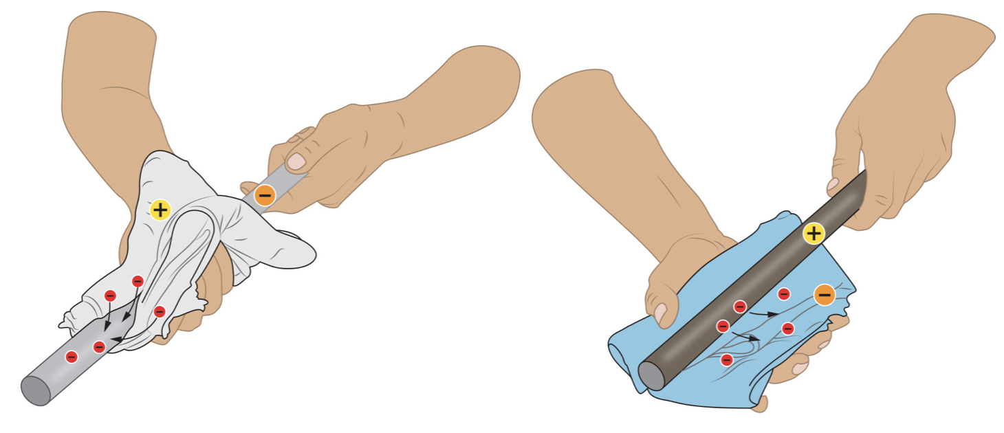
When you rub a woollen cloth on a PVC pipe, it will attract paper shreds. Because of the pipe being rubbed, it has become electrically or statically charged. Electrically / statically charged, is the situation in which an object has an electrical charge.
Positive and Negative Charges
If you rub a silk cloth over a perspex rod, the rod will become charged. However, there is a difference between the charges that were given to the perspex rod and PVC pipe. Two charged rods repel each other, same goes for two charged pipes. But a charged rod and charged pipe attract each other.
One type of charge is called positive (plus) and the other type is called negative (minus). A rod that is rubbed with a silk cloth has a positive charge. And a PVC tube that has been rubbed with a woollen cloth has a negative charge. A Positive charge is the charge that a neutral object gets when it loses electrons; and a Negative charge is the charge that a neutral object gets when it takes up electrons.
Electrons
An uncharged object contains the same amount of positive and negative charge. Therefore you don’t notice that an object contains any charges, this is called to be neutral. Neutral, is when the positive charge of an object is equal to the negative charge. You can give some objects an electric charge by rubbing them with a cloth. It has been discovered that small, negatively charged particles ‘jump’ from the cloth to the object, or the other way round. These particles are called Electrons. For this there are two options.
- The electrons go from the cloth to the object, the object then has a surplus of electrons. It is negatively charged overall. The cloth lost electrons so is now positively charged.
- The electrons go from the object to the cloth, the opposite happens then. The object loses electrons and becomes positively charged. The cloth gets extra electrons and becomes negatively charged.
Protons
An object’s positive charge is also due to particles, which are called protons. In a solid, protons cant move from one object to another. So when rubbing an object, you are always moving electrons with a negative charge around, and never protons with a positive charge. Protons, are positively charged particles and electrons are negatively charged particles.
Voltage
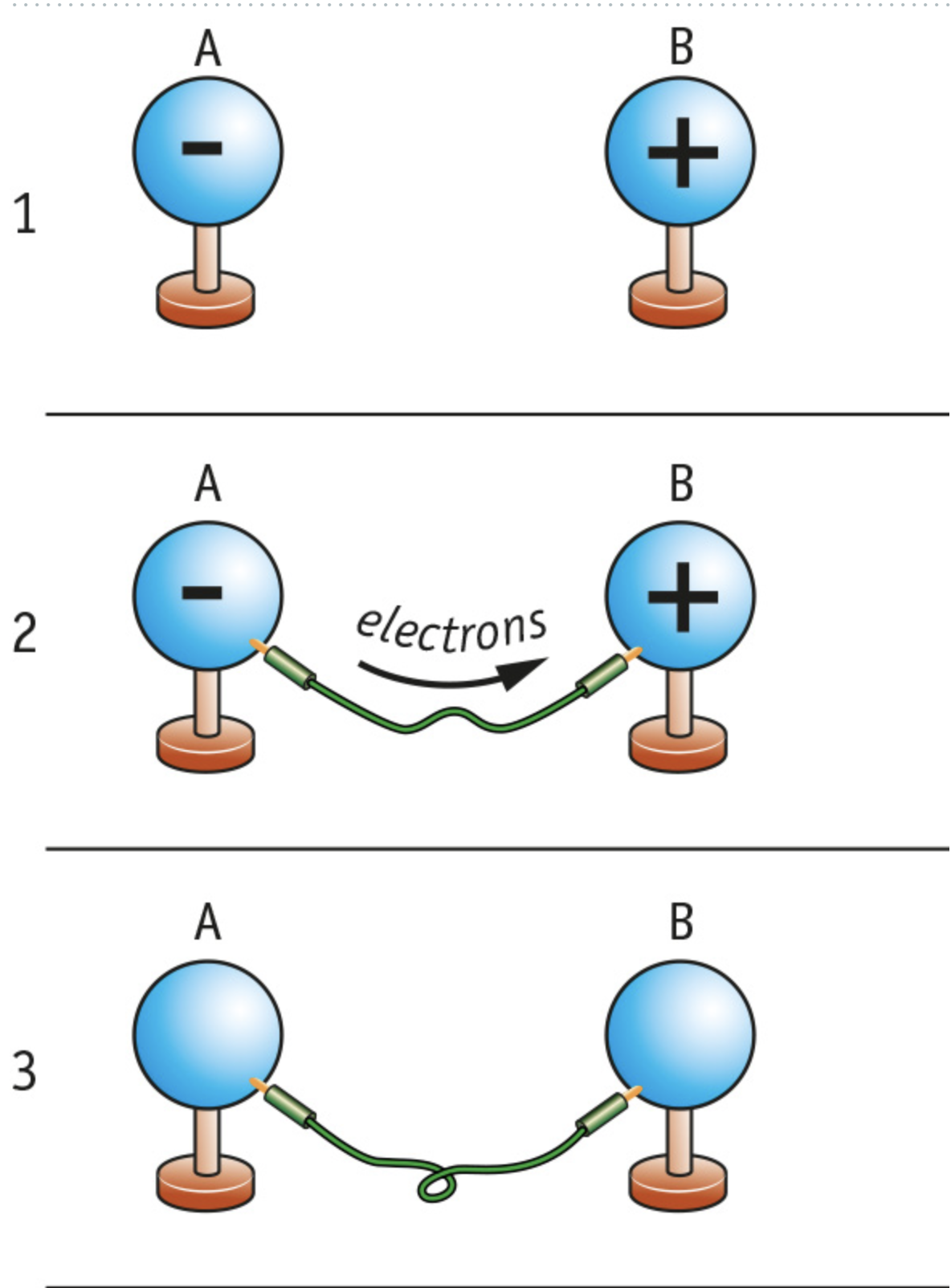
The picture above shows two equally large metal balls on plastic stands. Ball A is negatively charged and ball B is positively charged. In such a case, we say that there is a voltage between A and B. When you make a conducting connection between A and B, electrons start to move from A to B. There is then an electric current.
Discharging a Voltage
The current between A and B only flows for a very short while. This is because there will soon no longer be voltage between A and B anymore; both balls will then have the same charge.
If there is a high voltage between a charged object and its environment, sparks may jump across. You can use a static electricity generator to generate a static charge with a high voltage. But a machine like that discharges very quickly. a Voltage is a measure of how much electrical energy each particle is carrying.
Charge
When a current of 1 amp flows through a wire, 6.2∙10^18 electrons move across a cross-section of that wire every second. The unit of charge, the coulomb (C) is based on the amp and the second. A current of 1 amp transports 1 coulomb of electrical charge in 1 second. What you could also say is; one coulomb is equal to the charge of 6.2∙10^18.
Charge and Current
The total charge that flows through a wire depends on the current and the time. This relationship is given by the formula Q = I ∙ t, where:
- Q, is the charge in coulombs (C)
- I, is the current in amps (A)
- t, is the time in seconds (s).
Concepts
- Electrically / Statically Charged: Situation in which an object has an electrical charge
- Electron: Negatively charged particle
- Negative Charge: The charge that a neutral object gets when it takes up electrons
- Neutral: Situation in which the positive charge of an object is equal to the negative charge
- Positive Charge: The charge that a neutral object gets when it loses electrons
- Proton: Positively charged particle
- Voltage: A measure of how much electrical energy each particle is carrying
5.2 Resistance
Learning Objectives
- [ ] You can explain how to determine the resistance of a wire or other component.
- [ ] You can do calculations using the relationship between resistance, voltage and current.
- [ ] You can explain the difference between ohmic and non-ohmic resistance.
- [ ] You can describe how the resistance of an NTC or LDR depends on other variables.
- [ ] You can explain how to set the desired resistance on an adjustable resistor
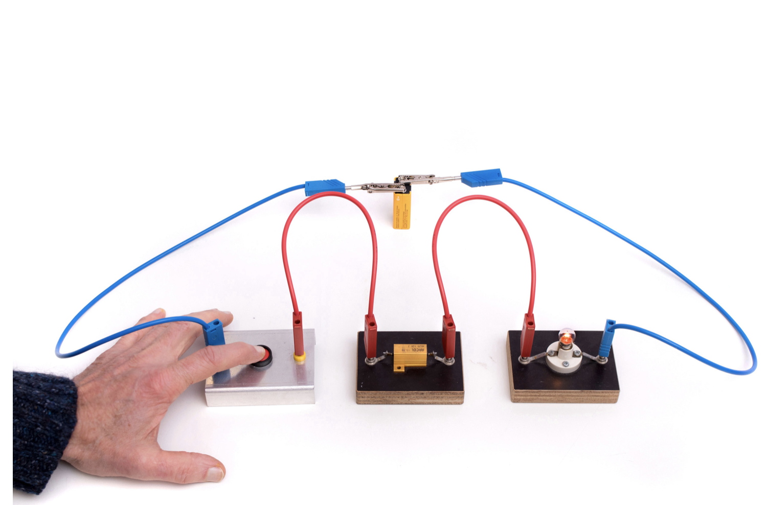
Voltage and Current
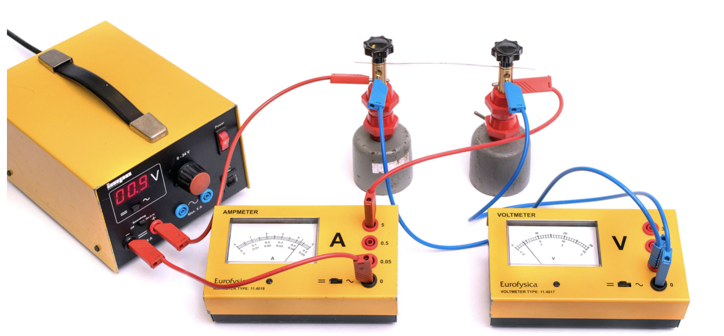
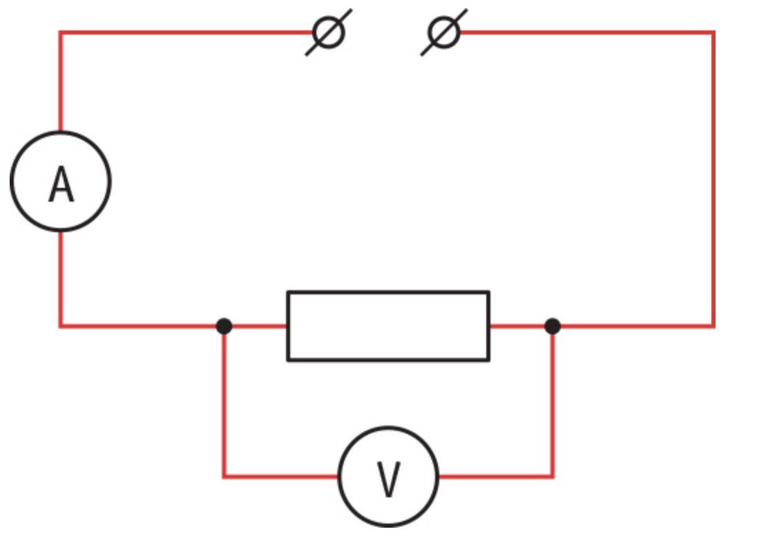
The setup in the picture below lets you measure the relationship between voltage across a wire and the current through the wire. The ‘voltage across a wire’ means the voltage between the two end of the wire. The picture after that shows the circuit diagram.
Resistance
If this experiment would be carried out with various wires, you will notice that the differences are large; some wires need a high voltage to ‘force’ a small current through the wire. A wire like this has a high resistance; it is difficult for currents to flow through it. There are also wires where a low voltage creates a large current. These wires have a low resistance: it is easy for currents to flow trough them. Resistance is the property of a component that determines how easily a electrical current flows through it.
You can define the resistance of a circuit component using the voltage (across) and the current (through). According to that definition, the resistance is equal to the voltage divided by the current. The formula for resistance is R = U/I, where:
- R, is the resistance in ohms (Ω)
- U, is the voltage in volts (V)
- I, is the current in amps (A)
(I,U) Diagram
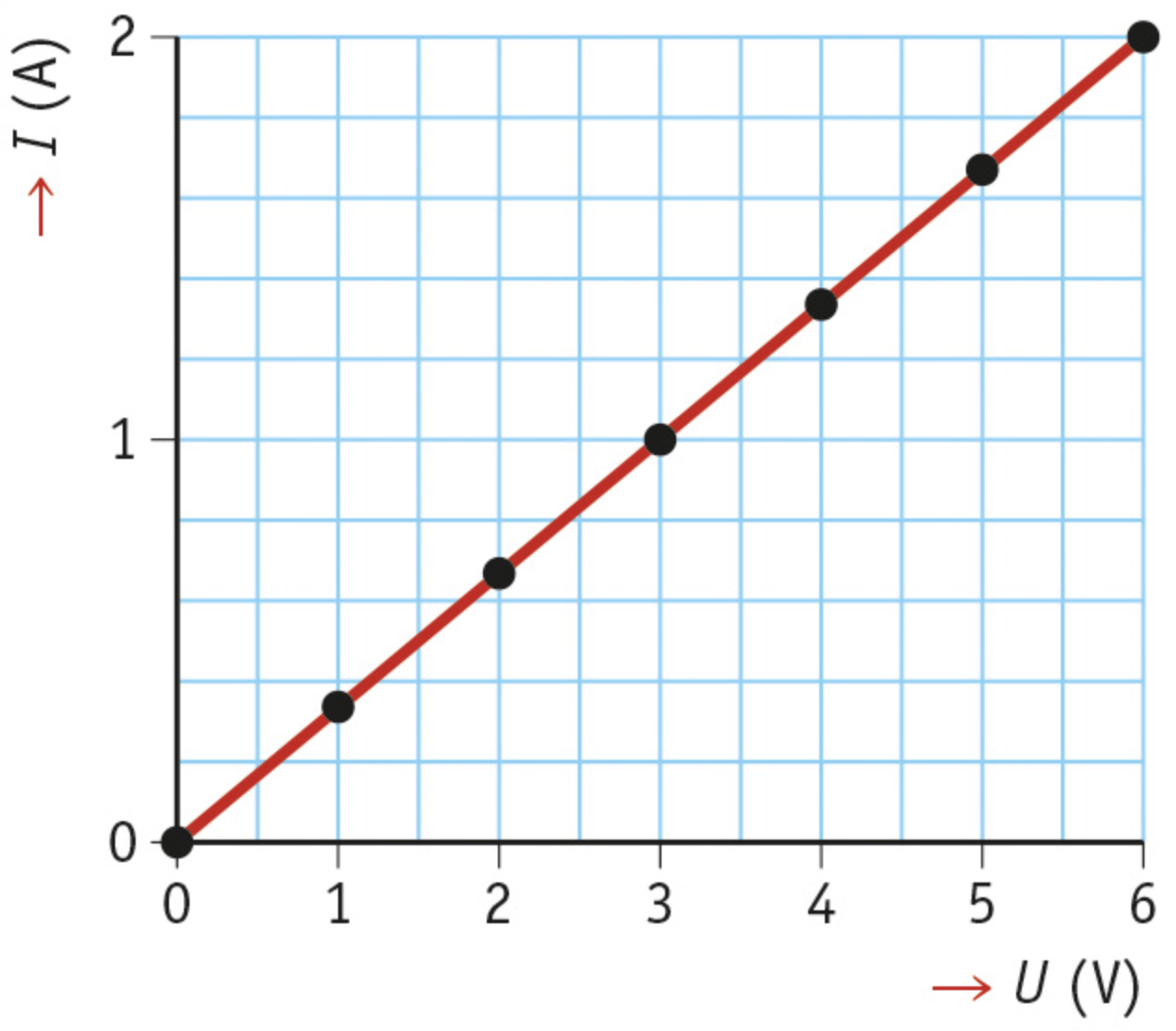
You can use the setup in the picture ‘how to determine the resistance of a wire’ to carry out a series of measurements in which you increase the voltage more and more. The results of such an experiment are drawn in the picture below, the experiment uses a wire of a metal called constantan. In the graph, the current has been plotted against the voltage. Such a graph is what we call an (I,U) diagram
Ohm’s Law
In the graph you see,
- If the voltage doubles, so does the current
- If the voltage triples, so does the current
- And so forth
Therefore; The voltage (across) and the current (through) are directly proportional
This rule is called Ohm’s Law. Ohm’s Law shows that the wire’s resistance has a constant value: If you divide the voltage by the current, you always get the same number. So the resistance is the same, whatever the value of the current. A resistance like this is what we call an ohmic resistance.
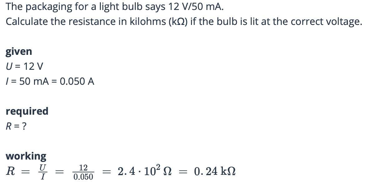
The Resistance of a Lightbulb
If you were to repeat this experiment with a lightbulb, you would get different results. You can see that in the picture below, the voltage and current are no longer directly proportional; when the voltage is doubled, the current visibly lags behind. The resistance is therefore increasing, you can also see that if you calculate the resistance for every point with the formula, in that case, Ohm’s Law does not apply.
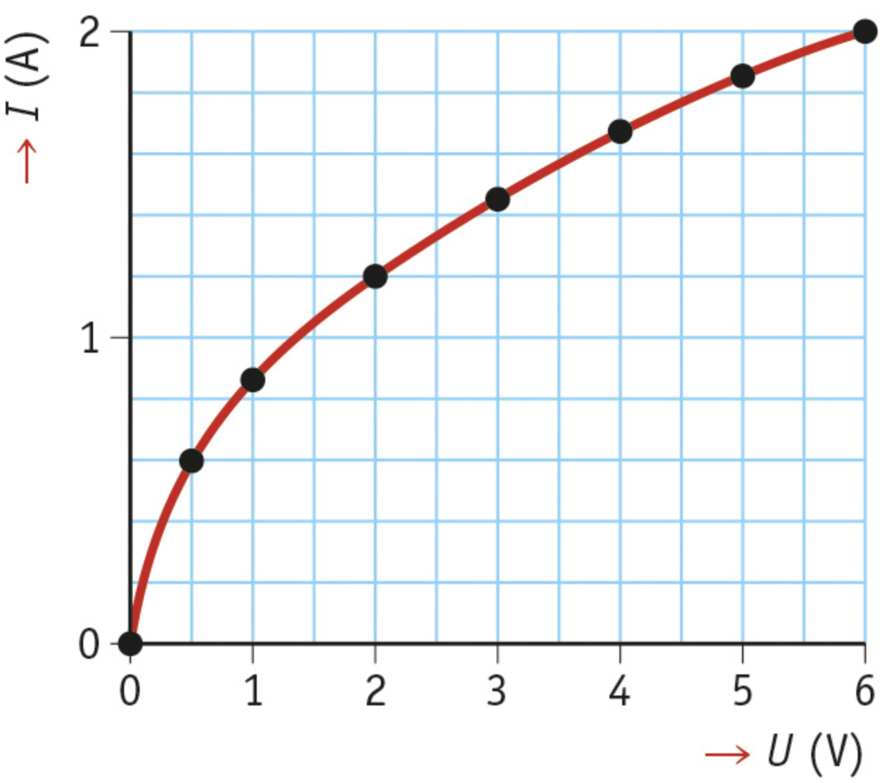
Resistance and Temperature
The fact that the resistance increases, has to do with the temperature. As the voltage across the filament increases, the bulb will light up more and more brightly. The temperature of the filament rises a lot, up to as much as 2500 °C. The resistance of the filament increases significantly at such high temperatures.
Almost all types of wires have a higher resistance when their temperature increases, but Constantan wires are an exception; their resistance is constant even when they become hot.
NTC and LDR
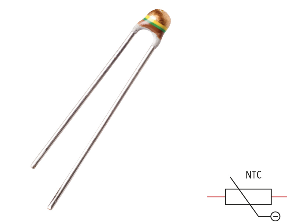
Circuits sometimes use component with variable resistance. Two examples of this are the negative temperature coefficient (NTC) and the light dependent resistor (LDR).
- An NTC is sensitive to changes in temperature. As the temperature of an NTC increases, its resistance becomes lower. The NTC will conduct much better then and pass more current.
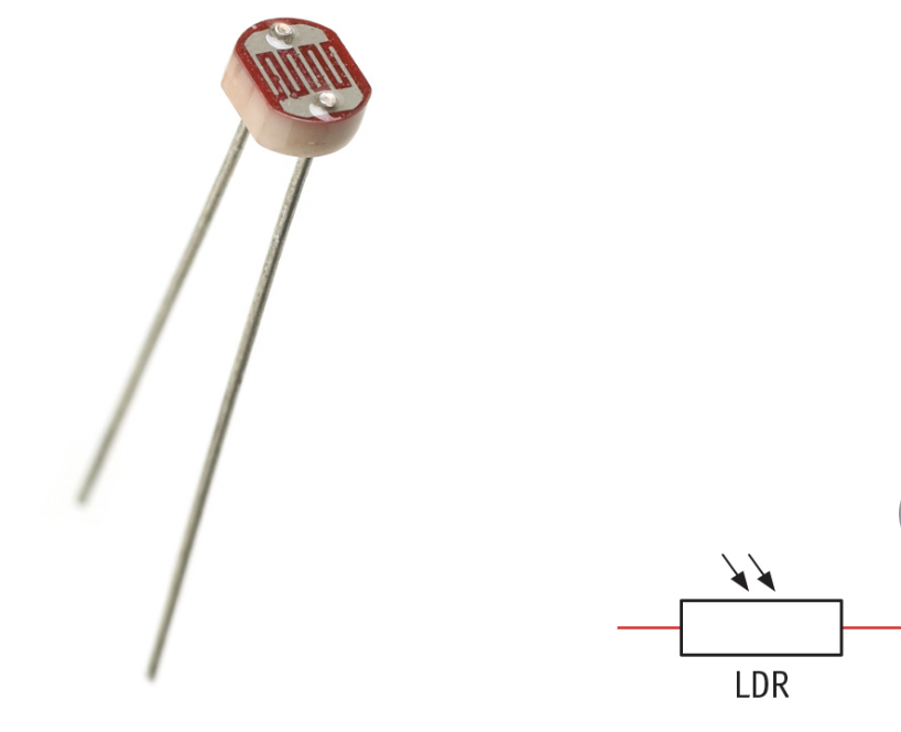
- An LDR is sensitive to changes in the amount of light. If more light falls on an LDR, its resistance will be lower. The LDR will conduct much better then and pass more current.
These variable resistors are widely used in automatic circuits: the NTC as a temperature sensor and the LDR as a light sensor
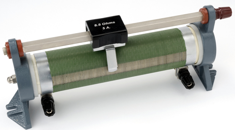
Variable Resistor
Another commonly used component is the variable resistor. It consists of a long, rolled up wire. You use a slider to control which part of the wire becomes part of the circuit. The shorter you make that part, the smaller the resistance. That lets you set the resistance to be the value you need it to be.
Concepts
- (I,U) Diagram: Graph showing current against the voltage
- LDR: A variable resistor that is sensitive to changes in the amount of light
- NTC: A variable resistor that has a higher resistance when the temperature is lower
- Ohmic Resistance: Resistor where the resistance is the same regardless of the voltage
- Ohm’s Law: The rule that says the voltage and the current are directly proportional
- Resistance: The property of a component that determines how easily electrical current flows through it
5.3 Connecting Resistors
Learning objectives
- [ ] You can explain the difference between a resistor (the component) and resistance (the variable)
- [ ] You can calculate the equivalent resistance to the resistors in a series circuit
- [ ] You can calculate the voltages U1, U2, U3 and so forth across each resistor in a series circuit
- [ ] You can calculate the equivalent resistance to the resistors in a parallel circuit
- [ ] You can calculate the currents I1,I2,I3 and so forth through each resistance in a parallel circuit
- [ ] You can explain how PTCs and NTCs work in circuits and demonstrate this with calculations. (plus)
Working with Resistors
If you connect a 6 V bulb to a 9 V voltage, the current gets too high and the bulb burns out. You can prevent this by increasing the overall resistance of the circuit. To do that, you place a resistor in series with the bulb.
Resistor and Resistance
Note the difference between ‘resistor’ and ‘resistance’: A resistor is an object, a component in a circuit, and the resistance is a variable, the number of ohms. For example: “this resistor has a resistance of 6Ω”
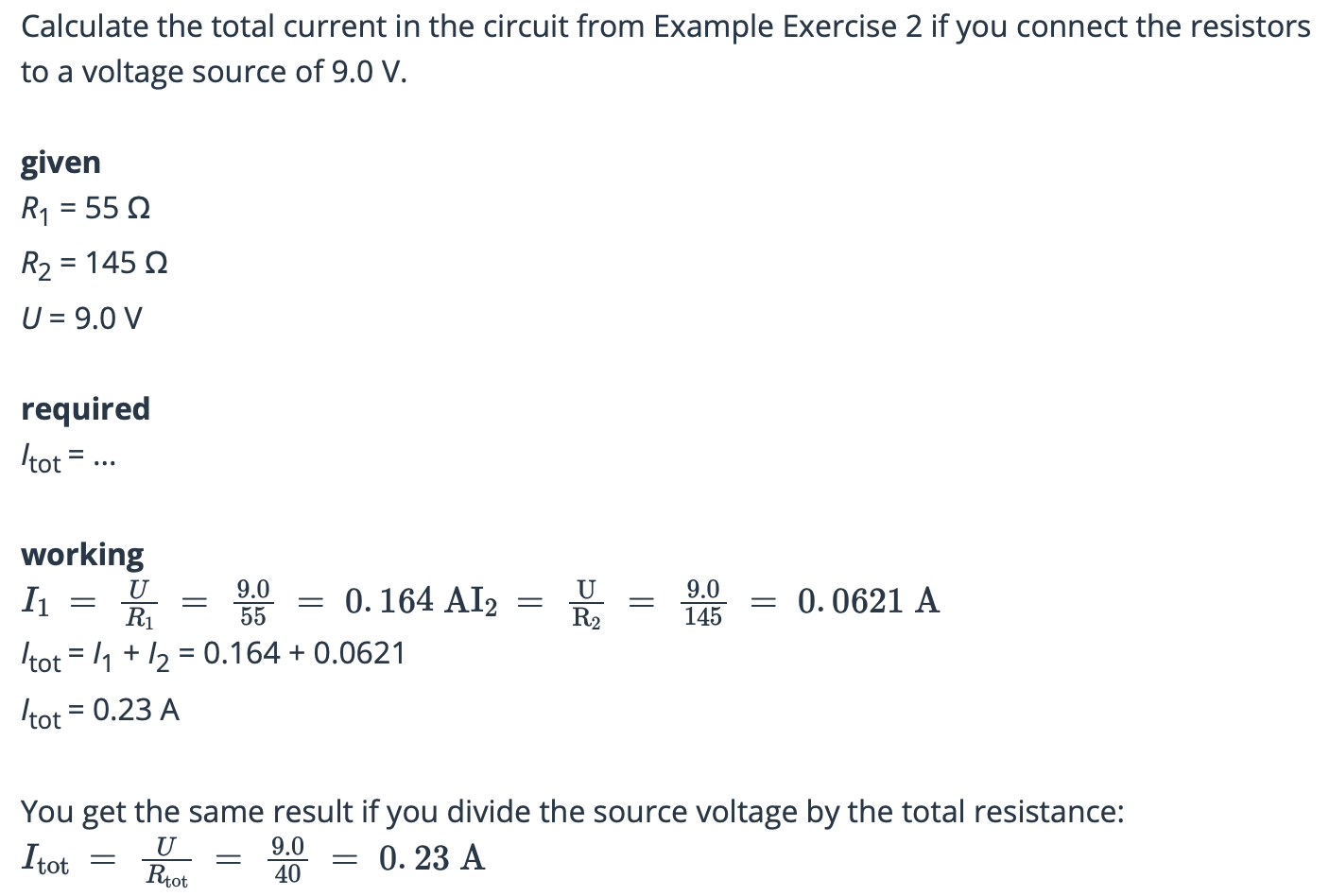
Resistors in Series
If you connect more and more resistors in series, the resistance of the whole circuit will continue getting higher. The current will decrease more if the voltage stays the same. You can calculate the total resistance by adding all the individual resistances. The formula for this is; Rtot = R1 + R2 + R3 + …, where:
- Rtot is the total resistance in ohms (Ω)
- R1, R2, R3 are the resistances of the first, second and third circuit components in ohms
Equivalent Resistance
If you replace all the individual resistors with a single resistor with the value of Rtot, it will have no effect on the rest of the circuit. That is why the total resistance is called the equivalent resistance. The equivalent resistance is the term for the overall resistance if multiple resistors are connected in series or in parallel.
Current and Voltage in a Series Circuit
The current I is equally high everywhere in a series circuit, there are no branches where the current has to split. However, the voltage in a series circuit is split across the various circuit components. If you connect two bulbs of the same type in series and connect them to a 9.0 V battery, each bulb will be lit at each 4.5 V.
If the two bulbs have different resistances, the source voltage Utot will not be divided exactly in two. Bulb 1 then has a voltage of U1 = I ∙ R1 and bulb 2 has a voltage of *U2 = I ∙ R2.*When you add them up, U1 and U2 equal the source voltage. The formula for this is; Utot = U1 + U2 + …, where:
- Utot is the voltage across the entire circuit in volts (V)
- U1, U2 are the voltages across the first and second circuit components in volts
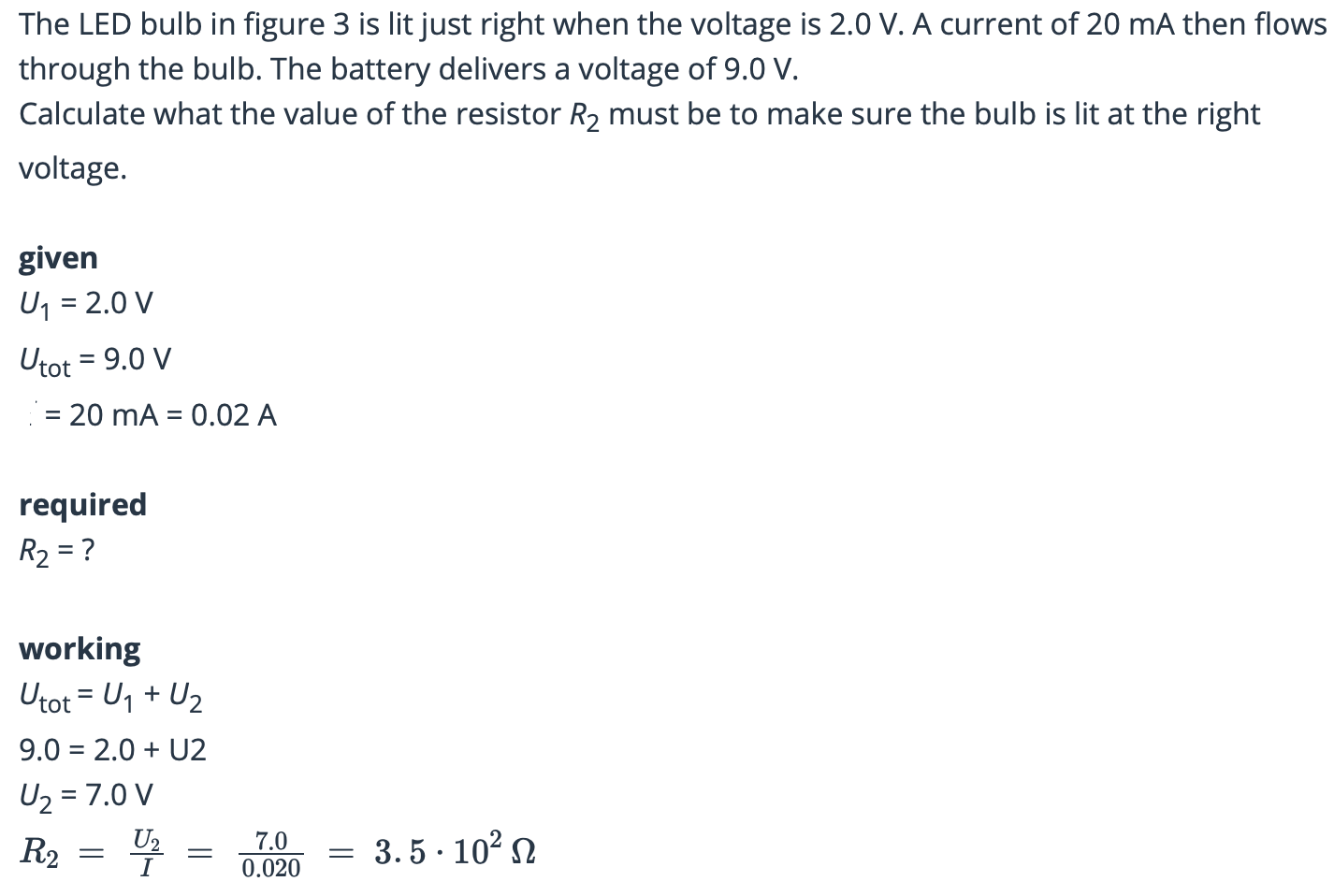
Resistors are often used to make sure that other component work at the correct voltage. Because the voltage of the battery is too high for the LED bulb, it is connected in series with a resistor. Only part of the voltage is then across the resistor. The rest is exactly high enough to make sure the LED bulb will be lit properly.
Resistors in Parallel
If you connect more and more resistors in parallel, the total resistance of the circuit will not be higher, as in a series circuit, but lower. That is because the number of branches increases, the current can flow more easily. If the voltage stays the same, the current will therefore keep increasing. This is why you cannot just keep connecting more and more appliances in parallel: the wires supplying the circuit could soon get overloaded. To prevent these overloads, a domestic electricity supply is divided into groups: each group can take a limited number of appliances.
Calculating the Total Resistance
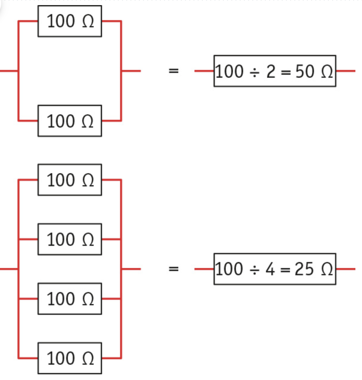
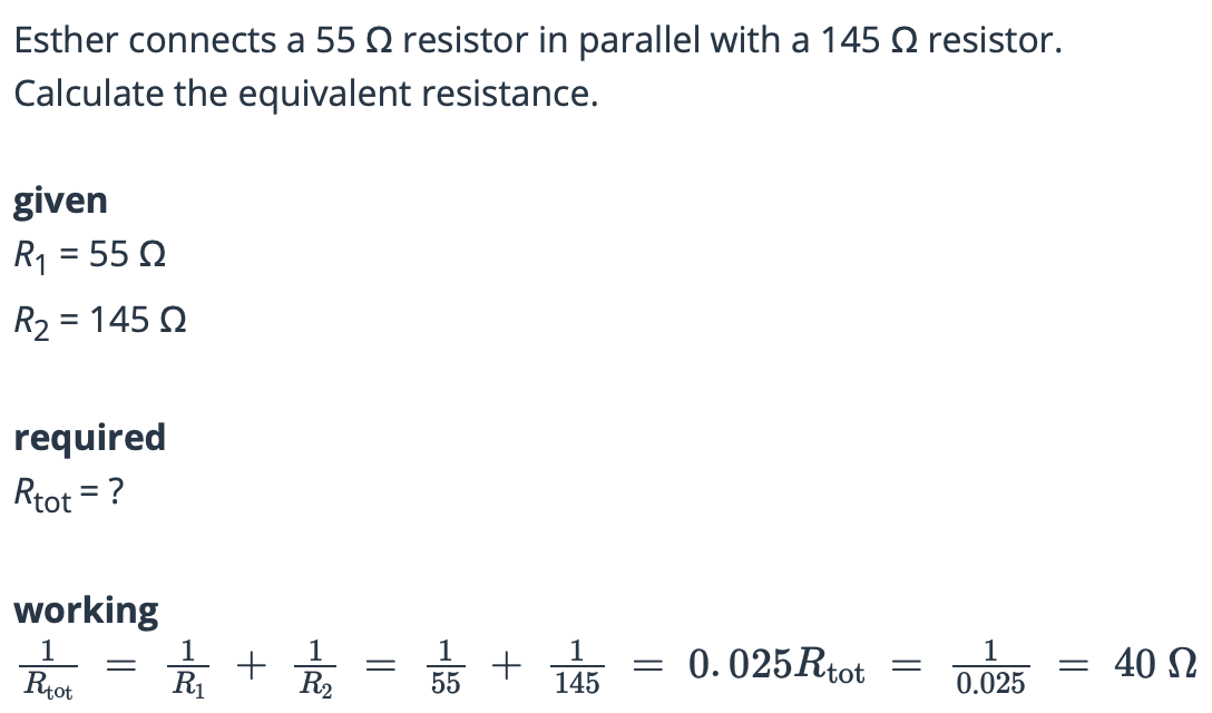
You can calculate the total resistance of a parallel circuit using the formula;
1/Rtot = 1/R1 + 1/R2 + 1/R3 + …, where:
- Rtot is the total resistance in ohms (Ω)
- R1, R2, R3 are the resistances of the first, second and third components in ohms
This formula shows that the total resistance is always lower than any of the individual resistors.
Current and voltage in a parallel circuit
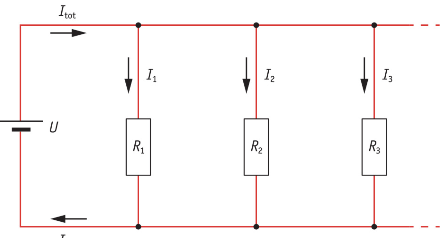
Each component in a parallel circuit is connected directly to the voltage source, this means that the full source voltage (Utot) is present across each component. The rule for voltage is: Utot = U1 = U2 = U3 …
In a parallel circuit the current is split between the various branches, you can see this in the picture below. The total current is the current in the part that is not split into branches; the power supply wires that all the current has to go through. You can calculate the total current with the formula; Itot = I1 + I2 + I3 + …, where:
- Itot is the total current in the unbranched part in amps (A)
- I1, I2 and I3 are the currents through the first second and third branches in amps (A)
Risk of Overload
There is a risk of overload in the part that is not split into branches, if too many circuit component are connected at the same time.
The PTC and NTC in circuits (plus)
A PTC works in the opposite way to an NTC. As the temperature of a PTC increases, its resistance increases too. PTCs and NTCs are sensitive to changes in temperature. This is why they are used a lot in circuits. Many appliances work best at normal temperatures. If the temperature of the LCD display on a phone gets too low, for example, the contrast is less. If an NTC is included in the circuit, the voltage across the chip that controls the screen increases and that makes the contrast go back up.
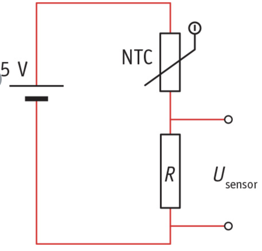
Resistors like these are also used in temperature sensors; circuits delivering a voltage that depends on the temperature. Temperature sensors also let the central heating come on automatically if it gets too cold, and cooling elements switch on in a freezer if it gets too warm.
The picture below gives an example of a temperature sensor using an NTC and a fixed resistor. As the temperature increases, the voltage across the fixed resistor does so too. You can then pass this voltage on to another circuit to for example, switch on a warning light.
PTCs are often used to protect component against currents that are too high. If a component is starting to heat up because the current is too high, the PTC’s resistance increases, which limits the increase in the current.
Concepts
- Equivalent Resistance: Overall resistance if multiple resistors are connected in series or parallel
- Total Current: The current in the unbranched part of a parallel circuit
5.4 Automatic circuits
Learning Objectives
- [ ] You can explain what the functions are of the sensor, the switch and the actuator in an automatic circuit
- [ ] You can describe how a transistor works when it is used as a switch
- [ ] You can draw a circuit diagram for a simple circuit with a transistor, such as a burglar alarm or an automatic streetlight
- [ ] You can explain how the circuits for a burglar alarm and an automatic streetlight work
Sensor - Switch - Actuator
Take lights that turn on and off by itself, such a light is operated by an automatic circuit that’s made up of three parts: a sensor, a switch, and an actuator. Each component has its own function.
- The sensor produces an electrical signal that gives information about the surroundings. This signals the switch if anything has changed in the surroundings
- The switch responds to the information sent from the sensor. If the signal from the sensor requires a response, it switches the power on or off.
- The actuator does something that is wanted at that moment: a light comes on, a siren starts sounding, a motor is started, and so forth.
Lights with Sensors
Some outdoor lights have a sensor that responds to the amount of the daylight. When it gets dark, the signal from the sensor changes and the bulb turns on.
Transistor
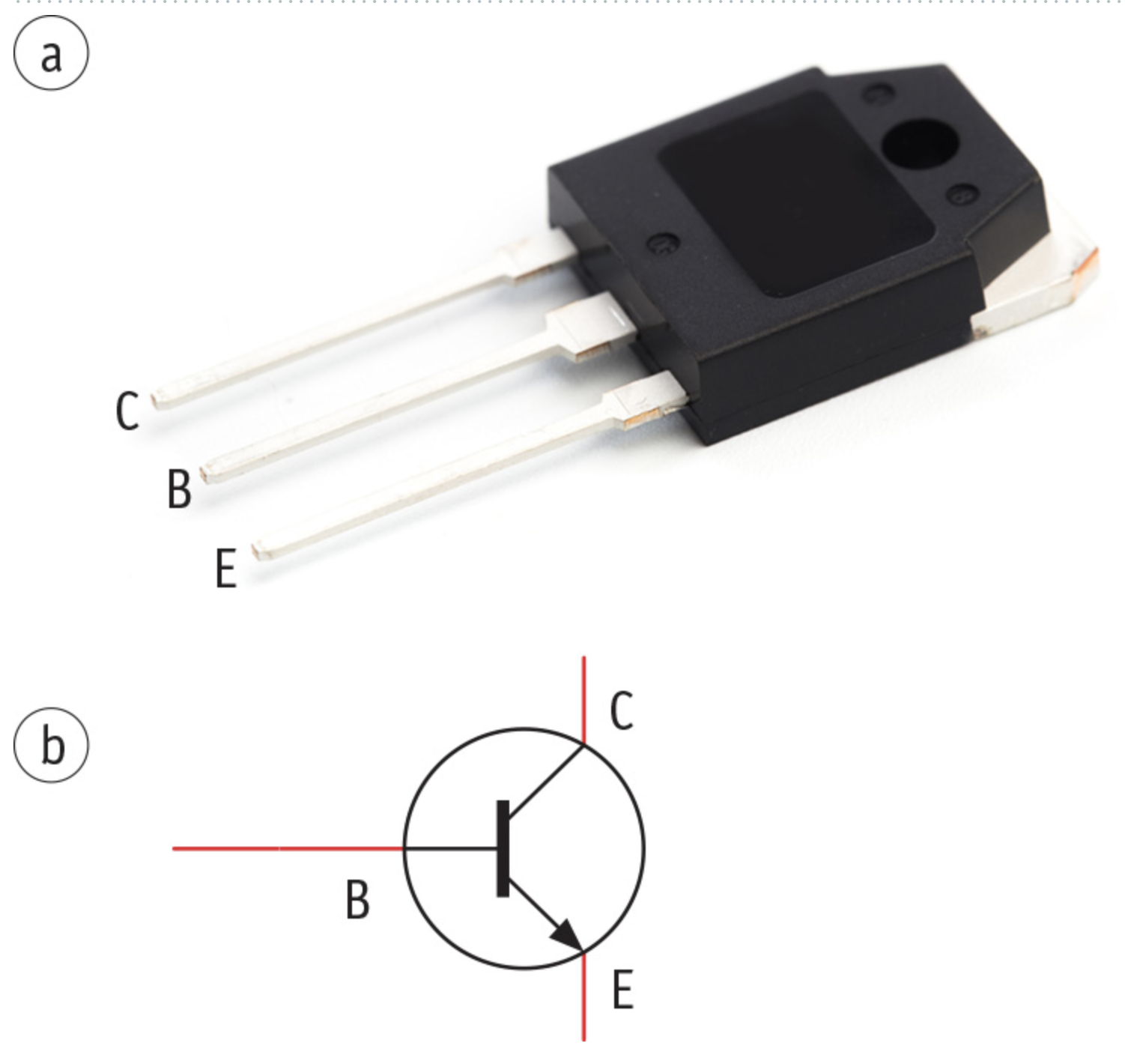
In many automatic circuits, the actuators are switched on and off by a transistor. In that case, such a transistor acts as an automatic switch. As shown in the picture below, a transistor has three terminals:
- The collector (C)
- The base (B)
- The emitter (E)
How a transistor works
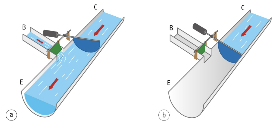
The way a transistor works can be compared to the way a traffic barrier works. A barrier is raised or lowered to allow the traffic on the road to pass or stop; a transistor does the same, but with the current to a device.
In the ON position, the transistor allows the current to pass, but in the OFF position it blocks the current;
- The transistor is turned to the ON position when a current flows from the base to the emitter. A larger current can then flow from the collector to the emitter.
- The transition is in the OFF position when no current, or very little current, is flowing from the base to the emitter. No current can then run from the collector to the emitter.
Current Limiters
You therefore use a small ‘switching current’ (B to E) to turn a much larger ‘collector current’ (C to E) on and off. If these currents get too large, a transistor can easily get damaged. That’s why there are often one or more resistors used in a circuit with transistors. They work as current limiters.
Concepts
- Actuator: Part of a circuit that performs the desired action
- Base: One of the three terminals in a transistor. The size of the current through the base determines whether the collector lets the currents through.
- Collector: One of the three terminals in a transistor. The size of the current flowing through the base determines whether the current flows through the collector.
- Emitter: One of the three terminals in a transistor
- Sensor: Part of a circuit that passes information on about the environment using an electrical signal
- Switch: Part of a circuit that switched the current on or off
- Transistor: Part of a circuit that functions as an automatic switch.
Examples
A Burglar Alarm
The picture below shows a burglar alarm with a wire on a pane glass. You can see the current is splits into two at A. The bulk of the current goes through the wire of the window back to the battery, very little current runs through the base, because it has a much higher resistance.
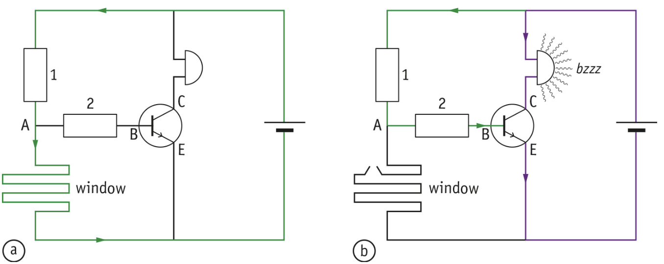
How a Burglar Alarm Works
The size of the switching current through the base is the signal that the transistor responds to. As long as the wire on the window stays undamaged, the switching current will be very small and the transistor stays off. No current runs from C to E. Resistor one and two make sure the currents that do flow stay as small as possible.
At part b of the picture above, someone has broken the window and the wire on the window is damaged. The current can now only flow back to the battery via the base. So the switching current from B to E is therefore much larger. The transistor reacts to this signal by switching to the ON position. A large current can now also flow from C to E; the buzzer starts working.
An Automatic Streetlight
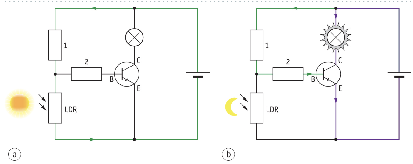
A transistor can also be used to build an Automatic streetlight. Two components in the circuit then have to be replaced; the wire on the windscreen is replaced by an LDR and the buzzer is replaced by a lightbulb. You can see this in the picture below.
When it is light outside, the resistance of the LDR will be small, almost all the current flows through the LDR and not through the base. The transistor stays off, and the bulb is not lit. When it is dark outside, the resistance of the LDR will increase, as a result more and more current will flow through the base. More current will flow through the bulb too. When it’s completely dark, the bulb will be fully lit.