Electromagnetic Induction
Whenever the magnetic field passing through a coil changes, an EMF appears.
Magnetic Flux
SI Unit: weber (Wb)
If the magnetic flux density over an area of 1m2 is 1 tesla then the flux through the area is 1 weber.
(B in the formula is perpendicular component of B)
Faraday’s Law of Electromagnetic Induction
The size of the induced EMS is directly proportional to the rate of change of the flux.
The bigger the EMF, the quicker the flux changes.
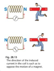
Lenz’s Law
The direction of an induced current is always such as to oppose the change producing it.
Generators
An electric generator is a device that converts mechanical energy to electrical energy.
e.g. electricity power stations, alternator in a car
A.C. Voltage
Root Mean Square Values of A.C
If we say A.C has a value of xA we are actually saying it has the same heating effect as xA D.C.
But as the A.C varies to have the same effect as the D.C its maximum value must be greater than xA.
This results in the following RMS values:
Mutual Induction
If a changing magnetic field in one coil causes an induced EMF to appear in a nearby coil there is said to be mutual induction between the two.
The bigger the induced EMF for a given rate of change of flux in the first coil the greater the induction.
Induction can be increased by decreasing the distance, winding the coils on the same soft iron core, increasing the number of turns on one or both coils.
Self Induction
Whenever the current passing through a coil changes, the magnetic field surrounding the coil changes. This changing magnetic field induces an EMF in the coil that opposes the changing current (i.e. back EMF)
A.C. and Inductors
A.C. is continually changing so as it changes the magnetic field is also changing and by the laws of electromagnetic induction (Faraday amd Lenz) an EMF is induced in the coil which always opposes the changing current.
A coil (inductor) opposes the flow of D.C. with its ohmic resistance.
A coil (inductor) opposes with flow of A.C. with its ohmic resistance and the back EMF induced.
Uses of Inductors
Smooth out slight variations in D.C. in power supply units.
Tuning circuits of radios to tune into different radio stations.
In dimmer switches.
Capacitors and A.C.
A charged capacitor blocks D.C.
A capacitor conducts A.C. since it chagres and discharges as the A.C. changes direction.
Transformers
A device used to change the value of an alternating voltage.
Input voltage across primary coil causes A.C. to flow in primary coil.
Causes an alternating magnetic flux in iron core.
This flux passes through secondary coil and induces EMF (output voltage).
The size of EMF depends on number of turns in the secondary.
Thus the output voltage can be greater, less or equal to input voltage.
Types of Transformers:
1. Step-up Transformer: Increases voltage. This happens when Ns (secondary turns) is greater than Np (primary turns). As a result, Vo (output voltage) is greater than Vi (input voltage).
2. Step-down Transformer: Decreases voltage. This happens when Ns is less than Np. As a result, Vo is less than Vi.
The ratio of input/output voltage matches the ratio of primary/secondary turns:
Uses of Transformers
Substations change the voltage from dangerous magnitudes (in overhead wires on the grid) to useable voltafes for use in the house.
All electrical items in your house contain transformers to supply the necessary voltages to their various parts.