ch. 4/5 - electromagnetism and the x-ray tube
1/74
There's no tags or description
Looks like no tags are added yet.
Name | Mastery | Learn | Test | Matching | Spaced |
|---|
No study sessions yet.
75 Terms
Magnetism
• The force exerted by a magnet when they attract or repel each other
Fundamental force (or force of nature)
Results from the motion of a charged atomic particle
magnet
object with a magnetic field
any charged object in motion has a magnetic field
orbital magnetic moment
anything moving point A to point B has a circular field of magnetism
Spin magnetic moment
moves around and around in a circle (spins on axis)
Magnetic dipoles
has a north and South Pole
magnetic domains
collection of dipoles put together.
the more dipoles put together, the stronger it it
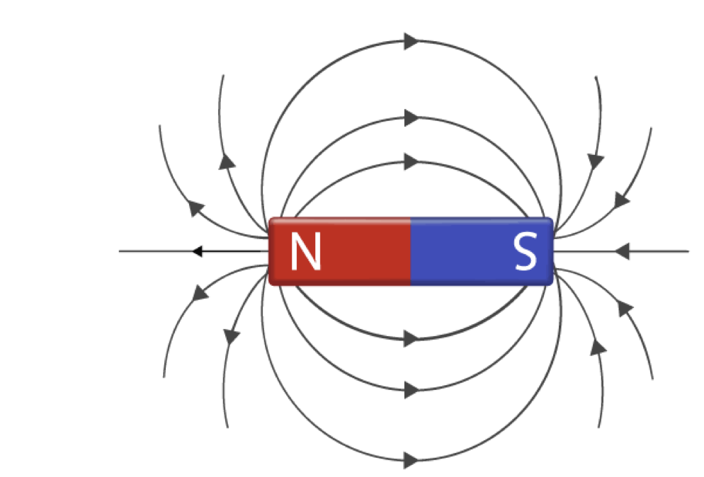
Lines of force (Lines of flux)
the lines around a dipole. stronger=more lines
measured in Wb
magnetic flux=
number of lines of flux in Wb
field strength/area
flux density
strength of magnet (more lines=more density= more strength)
Direction of flow
direction of lines of flux
Outside magnet
Inside magnet
Lines of force NEVER intersect
Forms a 3-dimensional force field around and through magnetic material
earth’s magnetism
The earth is a magnet
A compass will align itself with the earth’s magnetic lines of force and indicate direction
Both north and south poles tend to drift
Classifications of Magnets
natural permanent, artificial permanent, electromagnets
Natural permanent magnet
when iron oxide orients and creates a natural magnet
ex. Lodestones
artificial permanent magnet
man made
Alnico
- Aluminum, nickel, cobalt
Electromagnets
Temporary due to moving electric current
When the current stops flowing, the magnetic field collapses
Laws of Magnetism
repulsion-attraction
inverse square law
magnets demonstrate polarity
repulsion-attraction
like poles attract
opposite poles attract
true for dipoles and lines of force
inverse square law
Force between two magnetic fields directly proportional to product of their magnitudes and
inversely proportional to square of distance between them
as it gets further away, intensity of magnetic fields decreases
I1/I2 = D2 ² / D1 ²
Magnets demonstrate polarity
• Magnetic poles
Regions of magnetism always exist as a dipole (N, S)
• No matter how small it gets
Inverse square law applies to:
Magnetism
Electric field
Gravity
Oersted’s experiment
Demonstrated a relationship between a moving electric charge and magnetism
Charge in motion will create magnetic field
Magnetic field is always perpendicular to direction of moving charge
Fleming’s Hand Rules
• Helps to remember the relationship between electricity and magnetism
- Hand thumb rules along conductor
- Hand thumb rules for solenoid
Fleming’s Right Hand Thumb Rule for a Straight conductor
• Hold a solid conductor in right hand
Wrap fingers around conductor with thumb placed adjacent to wire
• Right-hand thumb rule
Thumb indicates direction of current (conventional flow, positive to negative)
Fingers indicate direction of magnetic field surrounding electrical conducting wire
Related to Lenz’s law
Solenoid
(type of electromagnet)
A coiled, helix of wire carrying an electrical current
strength of electromagnet depends on the amount of coils
detent=lock in the ceiling, type of electromagnet/solenoid. locks x-ray tube at a specific distance for proper SID
Two Primary Laws of Electromagnetics
• Both laws govern the induction of current by magnetic fields
• Faraday’s Law
First law of electromagnetics
• Lenz’s Law
Second law of electromagnetics
Three ways to create motion between lines of force and a conductor (to create an electric current)
Move the conductor
Move the magnetic lines of force
Vary the magnetic flux (objects are stationary, but field is moving)
Four Factors of Faraday’s Law
These four factors regulate the strength of induced current when magnetic lines of force and a conductor are in motion relative to one another:
if these factors are increased, strength of current increases (directly related)
1. Strength of magnetic field
2. Speed of motion between lines of force and conductor
3. Angle between lines of flux and conductor (increase or decrease area)
4. Number of turns in conductor coil
Lenz’s Law
• Applied Faraday’s law to his new discovery
• Induced current flow creates a magnetic field opposing the action that produced the original current
if you induce a new current, they will oppose each other since you can’t create new energy (one goes up, the other goes down)
Self-Induction
• Single coil
• Always present in coils supplied with alternating current
• Constantly changing current polarity (+)(-) or (-) (+)
Changing magnetic field
Induces voltage opposing original current
Inductive reactance
The tendency of alternating current to exist
Dependent on current supplied to the coil
Mutual Induction
• Two coils brought close together, one has a charge, other doesn’t. Creates a charge in the other
• Varying current supplied to primary coil and therefore varying EMF
• Induces current in secondary coil
• Two coils are electrically insulated from each other
supplied by AC (alternating current)
Generators
• Convert mechanical energy to electrical energy
• Can produce direct current or alternating current
• Components:
o Armature (coil of wire)
o Magnets
o Slip rings
o Brushes
Motors
• Convert electrical to mechanical energy
• Similar components to generators
• Armature supplied with current
Devices Controlling Electrical Current
• Transformers
• Autotransformers
• Capacitors
• Note:
These three devices are now miniaturized in chip technology!
Transformers
• Work on principle of mutual induction and Ohm’s law (V=IR)
• AC current
Electrons move in one direction and reverse
Allows variation of voltage levels
All electric power is transmitted this way from generating facilities to end users
• Two coils
Current supplied to primary coil
Induced voltage on secondary coil
Coils are electrically isolated from each other
Step-up transformer
voltage is increased from primary coil to secondary coil
step-down transformer
Voltage is decreased from primary coil to secondary coil
Transformer Types that use Mutual Induction
• Air Core
two coils close to each other
• Open Core
primary and secondary coil are filled with an iron core
• Closed Core
has iron enclosed in top and bottom
• Shell type
Most efficient
Most common
Used by X-ray generators
two closed core together
Autotransformers (Variable Transformers)
• Two designs:
Primary and secondary coils connected in series (instead of insulating them like we saw with mutual induction)
Single coil on central core
Both are considered self induction
• Primary side is supplied with varying current
• Used to select kVp of x-ray exposure
Basic X-Ray Circuit
Divided into three divisions:
1. Low voltage circuit (main circuit)
2. High voltage circuit (main circuit)
->AKA high tension circuit
3. Filament circuit
Capacitors
• Accumulates and stores electrical charge/energy
• Charged with direct current (DC) voltage
Electrons move in one direction only in a direct stream
• Simple design
• Useful in mobile xray units for small body parts
Can’t handle thick body parts due to voltage drop
Rectification
Process of changing AC to DC
• Half-wave rectification (suppresses/ignores half of the current)
• Full-wave rectification
• Located in high voltage section
Rectifiers
Solid-state diodes
Vacuum-tube rectifier
• Considered obsolete
Solid-State Diodes
Rectifier used in x-ray machines
• Solid state design acts like a “one-way gate” (direct current)
• Uses p-n junction semiconductors
n-type material (loosely bound electrons relatively free to move)
p-type material (holes or spaces where there are no electrons)
Electrons flow from the n side (-) to the p side (+)
Need for Rectification in X-Ray Circuits
• X-ray tubes require D C
• Rectification ensures only D C is applied to x-ray tube with 4 solid state diodes (full wave rectification)
Electrons travel from cathode (-) to anode (+)
• Current passing from anode to cathode is very damaging to x-ray tube because it would create way too much heat!
• The way the x-ray circuit is built protects from current that can damage the equipment
Thermionic Emission
• Electrical process of liberating electrons from a wire filament
• Filament is heated to very high temperature due to creating resistance with it’s small diameter
Filament is typically tungsten
• “Boiling off” electrons create an electron cloud around filament
• Principle of an incandescent light bulb
• Very important to x-ray tube design
4 Conditions for the Production of X-Rays
1. Source of electrons
come from the Cathode filament
2. Target
Tungsten anode
3. High-voltage (kVp)
4. Vacuum
X-ray tubes work on the principle of electrons flowing through a vacuum
Cathode Assembly
• Filament
Coiled tungsten wire helix
• Focusing cup
• Associated wiring
Low voltage side of x-ray circuit
Source of electrons
3 main functions of the cathode (-)
produce a thermionic (electron) cloud (main function)
increase kVp
focus/direct electrons toward the target
Filament
• Dual Focus
• Thermionic emission
• Coil of thoriated tungsten (thorium makes it a better conductor)
0.1–0.2 millimeter (mm) thick
1–2 mm wide
7–15 mm long
• Tungsten used because of high melting point
3,370°C
tiny, electrons have trouble getting through so creates high heat
Thermionic Emission
• Electrical process of liberating electrons from a wire filament
• Filament is heated to very high temperature due to creating resistance with it’s small diameter
Filament is typically tungsten
• “Boiling off” electrons create an electron cloud around filament
• Principle of an incandescent light bulb
• Very important to x-ray tube design
Focusing Cup
points in the direction of target, has a small filament to allow electrons out, focusing them
• Composed of nickel
• Low negative potential applied
• Compresses or narrows thermionic cloud
“space charge”
• Space charge effect
Congested electrons limiting current flow
Limits exposure milliamperes (mA) to 1000–1200
electron cloud is sitting, more electrons are piling, potential charge grows, low kVp
• Saturation current
Typically controlled by x-ray circuitry (kVp)
Higher kVp gives a bigger push of electrons towards to the anode
Eliminates the space charge effect
when we use kVp/exposure to move electrons
mAs
miliamperes-second
# electrons (intensity)
current
kVp
kilovoltage peak
strength of beam
penetrability
Grid-Biased Tubes
• Precise control of thermionic cloud (exposure)
• Briefly changes charge of focusing cup from negative to positive
Attracts electrons and stops electron flow
• Permits very short, rapid sequencing of exposures
Starting and stopping the xray beam over and over
• Commonly used in:
Angiography
Pulsed fluoroscopy
Tube Failure (Cathode)
• Tube arcing
Vaporized tungsten collection on envelope because it gets so hot (metal envelope collects less than glass)
• Filament breakage
“Boost” and hold (push all the way down) vs repeated tube “boosting” (push exposure button down halfway first)
Filaments become increasingly thin due to vaporization over time (too much heat)
Most modern x-ray tubes will last between 10,000-20,000 exposures
Anode Assembly
• Three components:
• Anode (with target) (focal track target)
• Stator
• Rotor
Anode Assembly
• Three functions:
• Target surface for x-ray production
• Conducts high voltage (recycles energy from cathode back to generator)
Maintains a closed-circuit pathway
• Serves as primary thermal conductor
Stationary Anode
Only used for low energy x-ray machines such as dental units
Rotating Anode
• Modern x-ray machines
constantly turn during exposure, creates a larger target
• Made of Tungsten–rhenium alloy
• High atomic number
Z# 74
Excellent for x-ray production
• High melting point
• Heat-conducting ability
Stator
• Wraps around the rotor outside the envelope
• Electromagnets consisting of copper windings
• Stator failure
Results in suboptimal anode rotation speed (rotor stops turning)
Immediate melting on target results from too much heat (bullet melt)
Rotor
• Ferromagnetic bars arranged in cylindrical pattern
• Inside stator and envelope
• Copper cylinder connected to anode disk by molybdenum stem
• Turns when stator is energized
Rotation speeds 3,000-12,000 r p m
• Ball bearings
Located inside the rotor
Silver plated
Reduces surface contact & friction
Tube Failure (Anode)
• Ball bearings worn by long use at high temperature
• Melting of the anode disk due to overheating
AKA rotor failure!
Stator fails and rotor ceases to turn
• Causes:
Overload
Poor power conditions
Mechanical failure
Target Area
• Portion of anode that electron stream contacts
on an angle of 12 degrees
made of tungsten
• Referred to by several names
Target
Focus
Focal point
Focal spot (actual)
Focal track
• Point source of x-ray photons
• This is where they are created!
4 required things for x-ray production
• A source of electrons through thermionic emission
• A means of accelerating the electrons (kVp)
• A means of decelerating the electrons (target)
vacuum
Actual focal spot
• Physical area where the electrons strike on the target
• Controlled by length of filament & target angle
• Small actual focal spot is mA limited (only so many electrons can strike because of how big it is)
small focal spot limits current
Effective focal spot
• Area that is projected out of the tube and toward the patient
• Controlled by the actual focal spot
how is the size of focal spot related to spatial resolution
• Impacts image spatial resolution (detail)
• Inverse relationship with focal spot size
• Smaller focal spot = increased (better) resolution
Line Focus Principle
• The relationship between the actual focal spot and the effective focal spot
• The size of the effective focal spot will depend on the angle of the target on the anode
• Most common target angles are 12 degrees
• Larger angle = larger effective focal spot
• Smaller angle = smaller effective focal spot
Anode Heel Effect
• Due to geometry of anode design (angled target)
• Results in variation of x-ray beam intensity along longitudinal axis of x-ray beam
Cathode to anode axis
Total beam intensity can vary as much as 45%
• More intense under cathode side of tube
• Intentional positioning of body parts can take advantage of heel effect
(beam hits the anode heel, electrons get absorbed, therefore weaker beam on the anode side)
Warm-Up Procedure
• Only for some xray machines (most digital machines do not require)
• Gradually warms anode
Prevents cracking glass envelope in older machines
Helps maintain vacuum
• Recommendations vary between x-ray tube manufacturers
• Should be performed if tube has been idle for an extended period of time
> 2 hours
Check with tube manufacturer
Envelope
• Heat tolerant Pyrex glass or metal
• Two functions
Supports anode/cathode assemblies
Maintains a vacuum to avoid debris and disturbances
• Modern tubes now metal
10ʺ long
6ʺ central diameter
2ʺ peripheral diameter
• Tube Window
Area constructed for x-ray beam to exit
Protective Housing
• Metallic; lead lined cast steel
• Supports x-ray tube
• Controls leakage and scatter radiation
Lead lined
• Isolates high voltages
• Provides mechanisms to cool tube
Cooling oil surrounding tube
Cooling fans
Water cooling in high-end tube designs
Off-Focus Radiation
• Undesirable part of the beam produced away from the target and therefore considered “off focus”
• Contributes up to 25 percent of total primary beam
Low energy and of no diagnostic value
Collimator design blocks a significant portion (very important to collimate!)
• Produces “ghosting” of image and reduces image quality
• Can be corrected with post processing in digital radiography
Extending X-Ray Tube Life
• Follow recommended tube warm-up procedures
• Avoid frequent and successive “boosting” of tube
• Use low mA settings when possible
• Avoid rough handling of x-ray tube head
• Listen for unusual sounds
Report these to service engineer via supervisor